


LED strips: types, uses, and how to choose the best one | The ultimate guide
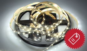
LED strips, also known as LED strips, LED tapes, or tape lights, represent one of the most significant innovations in solid-state lighting over the past decades. These flexible devices have radically transformed lighting design by offering versatile, efficient, and creative solutions for a wide range of applications.
The popularity of LED strips has grown exponentially due to their ability to combine energy efficiency, installation flexibility, and advanced control capabilities. This technical article provides a comprehensive overview of LED strips, analyzing their operating principles, construction features, performance parameters, and professional installation procedures.
Technical Definition
An LED strip is a flexible substrate, typically a flexible printed circuit (FPC), onto which multiple light-emitting diodes (LEDs) and auxiliary electronic components are mounted in series or series-parallel configurations, designed to operate at low voltage and provide continuous or segmented linear illumination.
Anatomy of an LED strip: components and construction
To fully understand the operation and potential of an LED strip, it is essential to examine its internal structure and constituent components.
Substrate and flexible printed circuit
The core of an LED strip is the flexible printed circuit (FPC), typically made of polyimide material or PET (Polyethylene Terephthalate) with a thickness ranging from 0.1mm to 0.3mm. This substrate hosts copper conductive traces, usually 1–2 oz thick (35–70μm), which distribute electrical power to the LEDs.
Light-emitting diodes (LEDs)
LEDs are the active elements of the strip. The construction characteristics of LEDs significantly impact final performance:
Chip size
Standard LED chip dimensions expressed in hundredths of a millimeter (e.g., 2835 = 2.8mm × 3.5mm)
Semiconductor material
InGaN for blue/green/white; AlInGaP for red/orange/yellow
Current-limiting resistors
Each segment of the LED strip includes current-limiting resistors, which are essential to ensure proper LED operation and prevent overload. The resistance value is calculated based on the supply voltage, LED forward voltage drop, and desired operating current.
Protective coating and encapsulation systems
Protection of electronic components is ensured by multiple layers of protective material:
| Layer | Material | Function | Typical thickness |
|---|---|---|---|
| Solder Mask | Photosensitive epoxy resin | Protects copper traces from oxidation and short circuits | 15–25μm |
| Silicon Coating | High-transparency silicone gel | Protects against moisture, dust, and mechanical stress | 0.5–1mm |
| Potting Compound | Epoxy or polyurethane resin | Complete sealing for extreme environments | 1–3mm |
Types of LED strips: technical classification
LED strips can be classified according to various technical criteria that determine their performance characteristics and application fields.
Classification by LED technology
LED strips can be categorized by multiple parameters, one of which is the type of LED chip mounted on the strip.
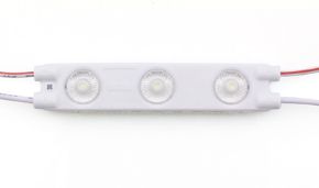
SMD (surface mount device)
SMD strips represent the most common technology for general applications. LEDs are soldered directly onto the PCB surface, ensuring a low profile and excellent thermal dissipation.
| SMD type | Dimensions (mm) | Typical power (W) | Lumens per LED | Main applications |
|---|---|---|---|---|
| 2835 | 2.8 × 3.5 | 0.2 – 0.5 | 20 – 60 lm | General ambient lighting |
| 3528 | 3.5 × 2.8 | 0.08 – 0.2 | 6 – 8 lm | Decorative lighting, low power |
| 5050 | 5.0 × 5.0 | 0.2 – 0.3 | 18 – 22 lm | RGB LEDs, color applications |
| 5730 | 5.7 × 3.0 | 0.5 – 1.0 | 45 – 60 lm | High brightness, task lighting |
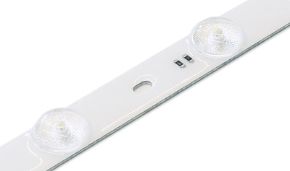
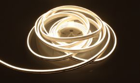
COB (Chip On Board)
COB technology represents the evolution of traditional LED strips. In this configuration, multiple LED dies are mounted directly onto the substrate and covered with a single phosphor layer, creating a continuous and uniform light source.
COB Technological advantages
- Light uniformity: eliminates the "dot effect" thanks to a continuous light source
- Power density: up to 300 LEDs per linear meter with minimal spacing
- Thermal efficiency: better heat dissipation due to the continuous active surface
- Emission angle: typically 160°–180° for omnidirectional lighting
CSP (Chip Scale Package)
CSP technology represents the cutting edge in LED integration. Chips are packaged nearly at the same size as the die itself, almost entirely eliminating traditional interconnect materials.
Classification by color configuration
A second key parameter defining an LED strip is the color of the emitted light, which can be monochromatic or multicolored.
Monochromatic LED strips
Monochromatic strips use LEDs of a single color, typically white at various color temperatures. Color temperature is measured in Kelvin (K) and determines the emitted light's hue.
| Color temperature | Hue | Typical applications | Color Rendering Index (CRI) |
|---|---|---|---|
| 2700K – 3000K | Warm White | Residential, hotels, restaurants | 80 – 95 Ra |
| 3500K – 4500K | Neutral White | Offices, retail, hospitals | 85 – 98 Ra |
| 5000K – 6500K | Cool White | Industrial, commercial, task lighting | 70 – 90 Ra |
| 6500K+ | Daylight White | Medical, museums, special applications | 90 – 98 Ra |
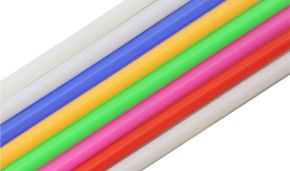
RGB and RGBW LED strips
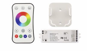
RGB strips combine red (R), green (G), and blue (B) LEDs to generate a wide color gamut through additive color mixing. RGBW strips include an additional white channel to improve white rendering and increase luminous efficiency in white mode.
RGB control configurations
RGB strips can be configured in two main modes:
- Common anode control: all LED anodes are connected together, requiring current-sinking controllers
- Common cathode control: all LED cathodes are connected together—this is the more common configuration for standard controllers
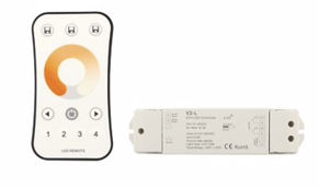
Tunable white LED strips
Tunable White (or Dim-to-Warm) strips combine LEDs of different color temperatures (typically 2700K and 6500K), allowing continuous adjustment of white light from warm to cool. This technology is especially valued in applications requiring circadian rhythm adaptation.
Classification by supply voltage
Another critical factor—once the maximum strip length has been determined—is the required supply voltage.
12V LED strips
12V strips are the standard for DIY and decorative lighting. They offer the advantage of higher electrical safety and the availability of affordable power supplies.
12V strip limitations
Due to voltage drop along conductors, 12V strips should not be daisy-chained beyond 5 meters. Longer installations require multiple power injection points.
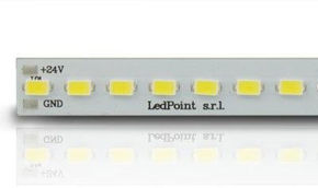
24V LED strips
24V strips are preferred for professional installations and high-power-density applications. Higher voltage reduces voltage drop, enabling power run lengths up to 10 meters with acceptable losses.
48V and high-voltage LED strips
High-voltage strips (48V, 120V, 240V) are used in industrial and commercial applications where long runs without intermediate power points are required.
Technical and performance parameters
Evaluating an LED strip's performance requires analysis of numerous technical parameters that determine suitability for specific applications.
Electrical parameters
There are six key electrical parameters to consider:
Operating voltage (Vf)
The nominal operating voltage of the LED strip, typically 12V, 24V, or 48V for low-voltage applications, and 120V/240V for high-voltage strips.
Operating current
The current drawn by the LED strip, measured in amperes (A) or milliamperes (mA). This parameter is essential for correctly sizing the power supply and connection cables.
Electrical power
The electrical power consumed by the LED strip, calculated as voltage multiplied by current (P = V × I), expressed in watts (W) per linear meter or for the total length.
Power calculation
To calculate total power required for an installation:
Ptotal = Length (m) × Power per meter (W/m) × Safety factor
The safety factor, typically 1.2, ensures the power supply does not operate at its maximum capacity.
Energy efficiency (lm/W)
Energy efficiency represents the ratio of luminous flux emitted to electrical power consumed, measured in lumens per watt (lm/W). Quality LED strips typically range from 100 to 180 lm/W.
Photometric parameters
There are four main photometric parameters:
Luminous flux (lumens)
Luminous flux measures the total amount of light emitted by the source in all directions, regardless of spatial distribution. It is measured in lumens (lm) and often specified per linear meter of LED strip.
Luminous intensity (candela)
Luminous intensity describes the amount of light emitted in a specific direction, measured in candelas (cd). This parameter is especially important for LED strips with secondary optics.
Illuminance (lux)
Illuminance measures the amount of light falling on a surface, expressed in lux (lx). 1 lux equals 1 lumen per square meter. Illuminance depends on distance and angle between source and surface.
Luminous distribution
Luminous distribution describes how light is emitted into the surrounding space. Standard LED strips typically have a 120° emission angle, though secondary lenses can modify this angle.
Chromatic parameters
We can identify three key chromatic parameters:
Correlated color temperature (CCT)
CCT describes the color appearance of light emitted by a source, expressed in Kelvin (K). Lower values (2700K–3000K) correspond to warm light, medium values (3500K–4500K) to neutral light, and higher values (5000K–6500K) to cool light.
Color Rendering Index (CRI)
CRI measures a light source’s ability to faithfully reproduce object colors compared to a reference source. CRI is expressed as Ra on a scale from 0 to 100, where 100 represents perfect rendering.
| CRI (Ra) value | Color rendering quality | Typical applications |
|---|---|---|
| < 70 | Poor | Decorative lighting, technical areas |
| 70 – 80 | Fair | General lighting, offices |
| 80 – 90 | Good | Retail, schools, hospitals |
| 90 – 95 | Excellent | Museums, art galleries, premium retail |
| 95 – 100 | Perfect | Medical applications, color analysis |
Extended Color Rendering Index (R9)
Beyond standard CRI (Ra), R9 is important—it specifically measures saturated red rendering. An R9 value above 50 is generally acceptable for quality applications, while values above 90 are required for critical uses.
Reliability and lifetime parameters
Reliability and lifetime can also be quantified by specific parameters, though these must be evaluated in the context of the installation environment.
Useful lifetime (L70, L80, L90)
The useful lifetime of an LED strip is defined as the time after which luminous flux drops to a specified percentage of its initial value (typically 70%, 80%, or 90%). Quality LED strips have an L70 lifetime ranging from 30,000 to 50,000 hours.
Operating temperatures
LED strips typically operate between –20°C and +40°C for standard models and –40°C to +60°C for industrial versions. Maintaining optimal junction temperatures is crucial for performance and longevity.
Ingress Protection (IP) Rating
The IP (Ingress Protection) rating classifies an LED strip’s resistance to solid and liquid ingress. The following table shows common IP ratings:
| IP Rating | Solid protection | Liquid protection | Applications |
|---|---|---|---|
| IP20 | Fingers and objects > 12.5mm | No protection | Indoor, dry areas |
| IP65 | Dust-tight | Water jets (6.3mm nozzle) | Kitchens, bathrooms, sheltered outdoor |
| IP67 | Dust-tight | Temporary immersion (15cm–1m) | Washdown areas, outdoor |
| IP68 | Dust-tight | Continuous immersion (>1m) | Fountains, pools, underwater |
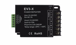
Power and control systems
Proper power supply and control of LED strips are essential to ensure performance, reliability, and long-term durability.
LED strip power supplies
Let’s now review the types of power supplies compatible with LED strips.
Power supply types
LED strip power supplies can be classified by construction technology and operational characteristics:
| Power supply type | Efficiency | Size | Cost | Applications |
|---|---|---|---|---|
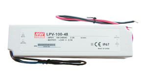
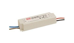
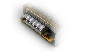
| Linear Power Supply | 40–60% | Large | Low | Simple, low-power applications |
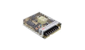
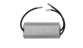
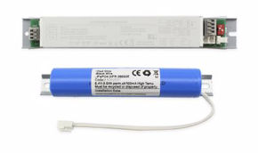
| Switching Power Supply | 80–95% | Compact | Medium | General, professional applications |
| Power Supply with PFC | 90–95% | Medium | High | Professional, high-power applications |
Power supply sizing
Correct power supply sizing is essential for optimal operation and system longevity. The power supply rating should be calculated as:
Sizing formula
Psupply = Pstrip total × Safety factor
Where:
- Pstrip total = Length (m) × Power per meter (W/m)
- Safety factor = 1.2 – 1.3 (20–30% margin)
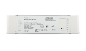
Example: For 8 meters of 14.4 W/m strip → 8 × 14.4 = 115.2 W × 1.25 = 144 W → Use a 150W power supply
Control systems
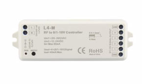
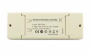
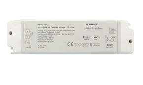
PWM (Pulse Width Modulation) controllers
Pulse Width Modulation (PWM) is the most common method for controlling LED strip brightness. This technique adjusts luminosity by varying the duty cycle of the control signal, keeping current constant during active pulses.
PWM parameters
- Switching frequency: typically 200Hz – 20kHz (>1kHz to avoid visible flicker)
- Resolution: 8-bit (256 levels) to 16-bit (65,536 levels) for high-precision control
- Duty Cycle: ratio of active time to total period, expressed as a percentage
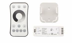
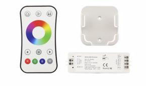
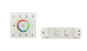
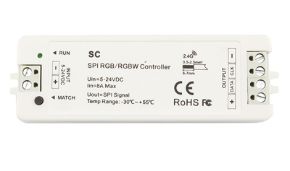
RGB and RGBW strip controllers
Color-variable strip controllers manage multiple independent channels—typically 3 for RGB (Red, Green, Blue) and 4 for RGBW (Red, Green, Blue, White). Common control protocols include:
| Protocol | Number of channels | Resolution | Transmission speed | Applications |
|---|---|---|---|---|
| DMX512 | 512 per bus | 8-bit / 16-bit | 250 kbps | Theaters, events, architectural |
| DALI | 64 addresses | 8-bit | 1.2 kbps | Building automation, offices |
| SPI | Unlimited (daisy-chain) | 24-bit per LED | 10+ Mbps | Video walls, artistic installations |
| Wireless (WiFi, Bluetooth) | Variable | 8-bit / 16-bit | 1–54 Mbps | Smart home, residential applications |
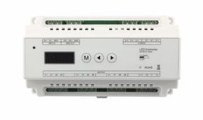
Intelligent control systems
Advanced control systems integrate features such as scheduling, occupancy sensors, daylight-responsive dimming, and integration with building automation systems (KNX, BACnet, LonWorks).
Professional installation and practical considerations
Correct LED strip installation is crucial for optimal performance, safety, and long-term durability. This section outlines procedures and technical considerations for professional installation.
Surface preparation
Before installing an LED strip, the mounting surface must be prepared to ensure both secure adhesion and long-term reliability.
Surface requirements
The installation surface must be:
- clean: free of dust, grease, moisture, and residues that could compromise adhesion
- smooth: uneven surfaces can cause pressure points and reduce adhesive effectiveness
- dry: residual moisture can impair bonding and promote corrosion
- dimensionally stable: materials with high thermal expansion can stress the LED strip
Chemical surface preparation
To maximize adhesion, it is advisable to treat the surface with:
- degreaser: isopropyl alcohol (IPA) ≥70% to remove oily residues
- primer: adhesive primers for difficult substrates (PP, PE, PTFE)
- activators: chemicals that increase the material’s surface energy
Power planning
Regarding power supply, it’s important to evaluate potential voltage drops—unless the LED strip features constant-current chips.
Voltage drop calculation
Voltage drop along the LED strip and power cables can compromise performance. To calculate voltage drop:
Voltage drop formula
ΔV = I × R × L
Where:
- I = total current (A)
- R = conductor resistance per unit length (Ω/m)
- L = conductor length (m)
For 12V strips, voltage drop should not exceed 5% (0.6V). For 24V strips, the limit is 3% (0.72V).
Power configurations
Depending on total installation length, different power configurations can be used:
| Configuration | Max length | Advantages | Disadvantages |
|---|---|---|---|
| Single-end power | 5m (12V) / 10m (24V) | Simple, cost-effective | Significant voltage drop |
| Dual-end power | 10m (12V) / 20m (24V) | Reduced voltage drop | Higher cable usage |
| Multi-point power | Unlimited | Minimal voltage drop | Complex, expensive |
Installation procedure
Let’s now examine the steps for installing an LED strip.
Cutting the LED strip
LED strips can only be cut at designated points, marked with a line and scissor symbols. Each cut point includes solder pads for electrical connection.
Cutting warnings
Cutting the LED strip at unauthorized locations will irreparably damage the circuit and render that segment unusable. Always use sharp scissors and make a clean, perpendicular cut.
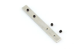
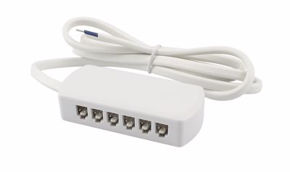
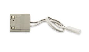
Connecting segments
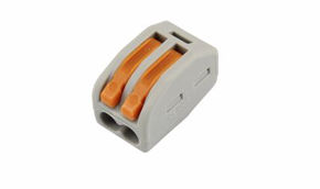
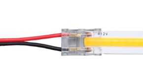
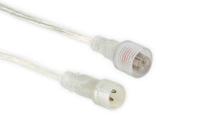
LED strip segments can be connected using:
- clip connectors: quick, solder-free solution—ideal for temporary installations
- soldering: permanent and reliable—requires specific skills
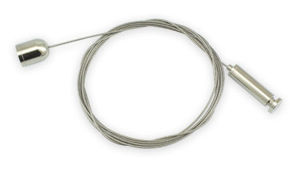
- pre-assembled connector cables: professional solution for complex installations
Soldering parameters
- Soldering iron temperature: 300–350°C for flux-core solder
- Tip contact time: 2–3 seconds per pad to avoid thermal damage
- Solder wire diameter: 0.8–1.0mm for optimal control
- Flux type: no-clean electronics flux
Thermal management
Importance of thermal dissipation
Proper thermal management is essential to:
- maintain luminous efficiency
- ensure chromatic stability
- extend LED lifespan
- prevent premature material degradation
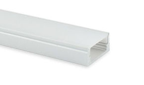
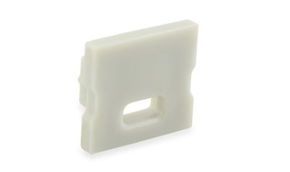
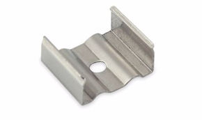
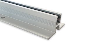
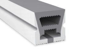
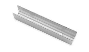
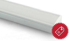
Aluminum profiles for heat dissipation
For high-power applications or high-temperature environments, it is advisable to use aluminum profiles specifically designed for LED strips. These profiles offer:
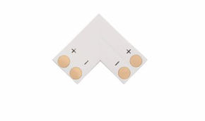
| Profile type | Applications | Advantages | Material |
|---|---|---|---|
| Corner | Corners, shelves, furniture | Easy installation, versatility | Aluminum 6063 or 6060 |
| Flat | Flat surfaces, ceilings | Optimal heat dissipation | 6063 Aluminum with thermal treatment |
| Round | Columns, tubes, curved structures | Adapts to curved surfaces | Flexible or segmented aluminum |
| With Diffuser | Where diffuse light is required | Protection and improved light distribution | Aluminum + PC or PMMA |
Maintenance and troubleshooting
A preventive maintenance program and the ability to diagnose common issues are essential for ensuring continuous LED system operation.
Preventive maintenance
It’s useful to inspect LED strips before failure occurs—a simple set of tasks requiring minimal time.
Periodic visual inspection
Perform visual inspections every 6–12 months to check:
- adhesive condition and mechanical mounting
- oxidation on contacts
- material degradation (silicone yellowing, deformations)
- surface cleanliness (dust buildup reducing efficiency)
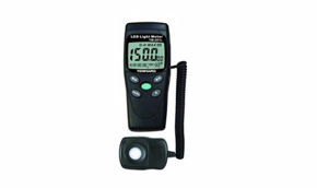
Electrical checks
Periodic measurements with a digital multimeter to verify:
- supply voltage at strip terminals
- current draw (compare with nominal values)
- electrical continuity between segments
- insulation resistance for outdoor or wet environments
Common problem diagnosis
Let’s now review the most common issues encountered with LED strips.
LED strip does not light
Systematic troubleshooting procedure:
- verify voltage at power supply output
- check wiring polarity (+ and –)
- inspect solder joints and connectors
- test strip with a known-good power supply
- check for short circuits.
Non-uniform or diminishing brightness
Possible causes and solutions:
| Issue | Probable cause | Solution |
|---|---|---|
| Brightness decreasing along strip | Excessive voltage drop | Dual-end or multi-point power injection |
| Intermittent or flickering segments | Oxidized connectors or cold solder joints | Repair connections, replace connectors |
| Color shift along strip | Phosphor thermal degradation | Improve heat dissipation, replace damaged segments |
| Dark spots or individual LED failures | Individual LED failure or circuit damage | Replace damaged segment |
RGB strip issues
Specific diagnostics for color-variable strips:
- incorrect colors: verify channel mapping on controller
- non-working channel: test channel directly with power supply
- erratic behavior: check controller-strip compatibility
- flickering: verify PWM frequency and power supply adequacy.
Advanced applications and use cases
LED strips are used across numerous sectors—from architectural lighting and signage to horticulture and healthcare.
Architectural lighting
In this context, it’s important to choose strips that are not only robust but also high-resolution.
Facade lighting
Facade lighting with LED strips requires high-quality products featuring:
- high IP rating (IP67 or higher)
- excellent chromatic stability (SDCM < 3)
- UV and weather resistance
- compatibility with DMX or DALI control systems
Accent and museum lighting
For illuminating artwork and valuable objects, LED strips must offer:
- very high CRI (CRI > 95, R9 > 90)
- negligible UV and IR emissions (< 75 μW/lm)
- adjustable color temperature (Tunable White)
- precise dimming control (0.1–100%)
Horticultural lighting
LED strips for horticulture represent a fascinating field—lighting can be used to support seed germination and plant growth.
Cultivation LEDs
Horticultural LED strips require precise spectral specifications:
| Spectral band | Wavelength | Plant effect | Recommended intensity |
|---|---|---|---|
| Blue | 400–500 nm (peak 450 nm) | Vegetative growth, compact foliage | 20–30% of total spectrum |
| Red | 600–700 nm (peak 660 nm) | Flowering, fruiting, stem elongation | 60–70% of total spectrum |
| Far-Red | 700–800 nm (peak 730 nm) | Photoperiod control, morphology | 5–10% of total spectrum |
| White | Full spectrum | Human vision, general growth | 10–20% of total spectrum |
Medical and healthcare applications
Another field for LlED strip use includes cleanrooms in operating theaters—where high brightness is essential during surgery—and chromotherapy rooms.
Operating room ighting
LED strips for medical environments must meet stringent requirements:
- CRI > 95 for accurate tissue assessment
- no flicker (PWM frequency > 20kHz)
- easy to clean and sterilize (IP68, smooth surfaces)
- electromagnetic compatibility (EMC) with medical devices
Light therapy
Specialized applications for treating conditions like Seasonal Affective Disorder (SAD) require:
- high luminous intensity (2500–10,000 lux at eye level)
- specific color temperature (5000K–6500K)
- full-spectrum daylight-like output
- no UV emissions
Future trends and technological developments
The LED strip industry continues to evolve, with emerging technologies and applications expanding their potential.
Miniaturization and micro-LEDs
The trend toward smaller LEDs (micro-LEDs < 100μm) will enable:
- densities exceeding 1000 LEDs per linear meter;
- sub-millimeter resolution for flexible displays;
- efficiencies above 200 lm/W;
- integration with flexible and stretchable substrates.
Integration with smart electronics
Next-generation LED strips will embed advanced features:
- integrated sensors (temperature, humidity, occupancy, ambient light);
- Li-Fi communication for data transmission via light;
- Power over Ethernet (PoE) to simplify installation;
- distributed AI-powered controllers for adaptive regulation.
Sustainability and circular economy
Development of more sustainable LED strips includes:
- use of recycled and recyclable materials;
- modular design for easier repair and replacement;
- reduction of critical materials (rare earths);
- improved efficiency to lower carbon footprint.
LED strips: useful but require careful evaluation
LED strips represent a mature yet continuously evolving technology that combines energy efficiency, application versatility, and advanced control capabilities. A deep understanding of operating principles, technical characteristics, and installation procedures is essential to fully leverage their potential in both professional and consumer applications.
With emerging technologies like micro-LEDs, smart system integration, and growing sustainability focus, LED strips will continue transforming the lighting landscape, offering innovative solutions across a wide spectrum of needs.