


How to test a power supply with a multimeter?
Today we want to focus on how to test a power supply with a multimeter, providing a methodology for the functional verification of power supplies and transformers using standard measuring instruments. This procedure represents a fundamental skill for technicians, installers, and professionals in the lighting sector.
Based on our experience in LED lighting power supply systems, we have created this guide to comprehensively address the frequent need for diagnosis and testing of electronic components.
Safety note: the procedures described involve handling live electrical circuits. We recommend adopting all personal protective measures and complying with electrical safety regulations. For work on high-power installations, we advise consulting qualified personnel.
How to test a power supply with a multimeter: preparation
The first step in testing a power supply is to obtain a digital multimeter (or tester), preferably of good quality, and ensure the probes are in good condition. Since safety is always important, we also recommend wearing insulated-soled shoes and working in a dry environment.
How to test a transformer with a multimeter
Let's start with the basics. The terms "power supply" and "transformer" are often used interchangeably, but there is a substantial difference. Testing a simple transformer—that is, a device that only steps voltage up or down—is a good starting point for understanding how these components work.
How to determine if a transformer is working?
Several steps are required to verify whether a transformer is functioning properly:
1. Isolation and safety: first and foremost, disconnect everything from the mains power;
2. Identification of windings: the primary winding (220V input) is generally recognizable by its thinner wires and higher resistance, while the secondary winding (output, e.g., 12V) has thicker wires;
3. Measuring winding resistance: once the wires are identified, set the multimeter to Ohm mode (Ω) and touch the probes to the two terminals of the primary winding. You should read a resistance value in Ohms (not infinite). If you see "OL" or infinity, the winding is open, meaning the transformer is faulty;
4. Checking for internal short circuits: when measuring resistance between the primary and secondary windings, or between a winding and the iron core, the reading must be infinite (OL). If continuity is detected, there is an internal short circuit.
5. Performing a no-load test (with power applied!): with great caution due to high voltage, reconnect only the primary winding to the 220V mains while leaving the secondary disconnected. Set the multimeter to AC voltage (V~) and measure the secondary output. This voltage should be close to the nominal value (e.g., 12V AC). If it reads zero or significantly lower, the transformer is faulty.
| Test | Multimeter mode | What to measure | Expected result | Anomalous result |
|---|---|---|---|---|
| Primary winding resistance | Ohm (Ω) | Between the two 220V input wires | A few hundred Ohms (e.g., 150Ω) | OL/Infinity (open) or 0Ω (short) |
| Secondary winding resistance | Ohm (Ω) | Between the two 12V output wires | A few Ohms (e.g., 1–5Ω) | OL/Infinity (open) or 0Ω (short) |
| Primary/secondary insulation | Ohm (Ω) high scale (MΩ) | Between one primary wire and one secondary wire | OL (no continuity, insulation OK) | Any resistance value (short) |
| No-load output voltage | AC Volts (V~) | Between the two 12V output wires (with primary powered) | ~12–14V AC | 0V or significantly below 12V |
How to test a power supply with a multimeter
Unlike transformers, power supplies—especially switching types used for LED strips—are more complex: they convert current (AC/DC), stabilize it, and regulate it, requiring a different procedure to verify proper operation.
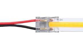
Identifying polarity
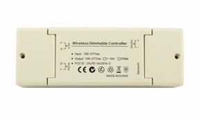
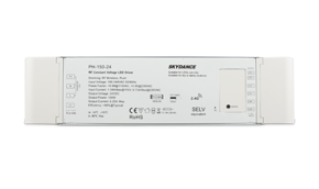
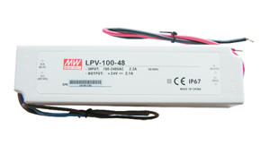
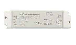
The power supply label displays all key specifications: output voltage (V DC or V~), current (A or mA), and power (W). In addition to these values, it is essential to check polarity: the connector symbol indicates whether the center pin is positive (more common) or negative. Set the multimeter to DC voltage mode, connect the black probe to the negative terminal (COM), and the red probe to the positive terminal (VΩmA).
Procedure
Below is a step-by-step procedure to test a power supply with a multimeter:
1. No-load test (without load): connect the power supply to the mains and measure the voltage at the output terminals. It should be very close to the nominal value (e.g., 12.0V for a 12V DC unit). If it reads zero, the power supply may be burnt out or in protection mode.
2. Load test (recommended): for a realistic assessment, connect a load (e.g., a 10W LED strip to a 12V/2A power supply). The measured voltage should remain stable, with only a small acceptable drop. If it collapses, the power supply is inadequate or faulty.
3. How to tell if a power supply is burnt out? In addition to zero output voltage, a burnt power supply may emit a burnt smell, show swollen components (especially electrolytic capacitors), or have a blown internal fuse.
Frequently asked questions
Many questions commonly arise before testing a power supply with a multimeter. Let's review some of them together.
1. What is the difference between a power supply and a transformer?
A transformer is a passive component that only changes the level of alternating voltage (AC). A power supply (or power supply unit) is an active device that typically converts mains voltage (AC) into a stabilized direct current (DC) voltage suitable for powering electronic equipment.
2. What are the symptoms of a faulty power supply?
- Flickering, pulsating, or completely unlit LED lights.
- Electrical humming or buzzing noise from the power supply.
- Excessive overheating.
- Absent or unstable output voltage (measurable with a multimeter).
3. What happens if I use a power supply with fewer amps (A) than required?
The power supply will become overloaded, overheat, and either go into protection mode (shutting off) or burn out. Rule of thumb: the voltage (V) must match the requirement exactly, while the power supply's current rating (A) must be equal to or greater than the load's demand. A 24V 5A (120W) power supply can safely run an LED strip consuming 80W, but an 80W power supply cannot reliably power a 120W load.
4. What happens if I use a power supply with higher voltage (V)?
This practice must be strictly avoided! Applying a voltage higher than the equipment's rating (e.g., supplying 24V to a 12V LED strip) will instantly destroy the LEDs. Voltage must always match precisely.
5. How can I tell if a power supply is regulated?
The label may include terms such as "Regulated," "Stabilized," or "Constant Voltage." Additionally, a regulated power supply maintains a nearly constant output voltage despite load variations. You can verify this by measuring the no-load voltage and then under load—the variation should be minimal (e.g., 0.1–0.3V).
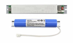
6. What are power supplies with backup batteries?
These are power supplies designed to operate LED emergency lights. They are standard power supplies that integrate a charging circuit and a battery. In the event of a blackout, they keep the lights on for hours.
7. Why do transformers or power supplies fail?
Common causes include: overload (too many watts connected), output short circuit, voltage surges, insufficient ventilation (especially for recessed models), and end of service life (particularly for electrolytic capacitors).
8. How do I measure a transformer's power rating?
Determining a transformer's exact power rating would require a variable load and precision instruments. In practice, it is sufficient to check the rating printed on the unit. If the label is unreadable, replace the component to avoid risk of failure.
Transformer losses
After reviewing how to test a power supply with a multimeter, we also wish to introduce the concepts of the short-circuit test (measuring copper losses) and the no-load test (measuring iron losses) for transformers. These tests cannot be performed independently and are laboratory procedures used to further assess efficiency. For typical installations, they are unnecessary—the multimeter test is more than sufficient for functional diagnosis.
How to test a power supply with a multimeter? Now you have the answer
We hope this guide on how to test a power supply with a multimeter—and on transformers in general—has clarified any doubts you may have had on the subject. If you need assistance choosing the right power supply for your LED installation, our support and assistance service is always available for any inquiries.