


High-density LED strips with 240 LEDs/m: when to use them, how to install them, and how to manage heat.
In the landscape of professional LED lighting, high-density LED strips have experienced a true silent revolution over the past five years: from a niche product used exclusively in luxury construction sites and high-end architecture studios, they have become the expected standard in quality residential and commercial projects, today representing over 38% of the total volume of LED strips sold in the Italian professional segment. This change is not accidental, but reflects a technical maturation of the sector and an exponential growth in the design awareness of architects, specialized electricians, and light designers who no longer accept compromises on the quality of the light produced.
The question that every professional asks when first approaching a technical specification with high-density LED strips is almost always the same: when is it worth switching from a standard 60 LED/m LED strip to a 120, 180, or 240 LED/m strip? Whenever the visual quality of light emission, light continuity, and color rendering are indispensable project parameters. But the complete answer requires an in-depth analysis not only of the optical characteristics of these strips, but of the entire chain of design and installation choices that determine their actual performance: heat management, aluminum profile selection, power supply voltage selection, diffuser type, maximum run length, and integration into the control system.
In this article, we will refer to thermal analyses with experimental data, comparative tables, photometric calculations, installation guides, and answers to the most frequently asked questions that typically arise on construction sites. The goal is to provide a solid knowledge base that allows you to specify, install, and maintain these products with maximum technical competence, avoiding the most common errors that lead to premature failures, unsatisfactory optical performance, or costly replacement interventions.
We will also analyze the physical phenomenon behind the dotting effect and how to eliminate it, delve into the thermodynamics of high-density strips with real temperature data, explore the function of aluminum profiles and the different types available, and finally arrive at regulatory considerations and market trends that are shaping the future of this segment.
What are high-density LED strips?
The term high-density LED strip is often used approximately in the market, with manufacturers and distributors applying this label to very different products. A rigorous technical definition is therefore the first step to correctly navigate an extremely varied supply landscape, where quality and actual characteristics can differ significantly from commercial claims.
Technical definition and classification by density
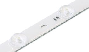
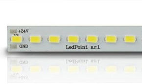
An LED strip is a flexible printed circuit board (PCB – Printed Circuit Board) on which a variable number of SMD (Surface Mount Device) LED diodes are mounted in series and parallel. The density of an LED strip is measured in number of LEDs per linear meter and represents the primary parameter that determines the quality of light emission in terms of uniformity and visual continuity. The generally accepted industrial classification includes the following categories:
| Category | LED/m | Spacing between diodes | Typical power (W/m) | Main application | Dotting effect |
|---|---|---|---|---|---|
| Low density | 30 LED/m | 33.3 mm | 2.4 – 4.8 W/m | Decorative backlighting | Very pronounced |
| Standard density | 60 LED/m | 16.7 mm | 4.8 – 14.4 W/m | General lighting, light cables | Pronounced (<50 cm) |
| Medium density | 120 LED/m | 8.3 mm | 9.6 – 19.2 W/m | Light cuts, suspended ceilings | Slight (<20 cm) |
| High density | 180 LED/m | 5.6 mm | 14.4 – 21.6 W/m | Quality architectural lighting | Almost absent |
| Very high density | 240 LED/m | 4.2 mm | 20 – 24 W/m | Premium light design, luxury, retail | Practically absent |
| Ultra density | 480 LED/m | 2.1 mm | 24 – 30 W/m | Displays, ultra-continuous light lines | Absent |
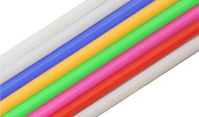
For the Italian professional market, the most significant category, the one that represents the true qualitative turning point in architectural applications, is that of 240 LED/m strips, which with a spacing between diodes of only 4.2 mm guarantees a practically continuous light emission, perceived as a homogeneous linear source rather than as a sequence of distinct luminous points.
Types of LED chips used in high-density LED strips
Understanding the types of SMD chips used in high-density LED strips is fundamental to evaluating the performance differences between apparently similar products. The chip size determines not only the physical dimensions of the diode but also its luminous efficiency, thermal behavior, and color rendering. In high-density strips, the most used chips belong to the following families:
| SMD Chip | Dimensions (mm) | Use in density | Typical efficiency (lm/W) | Emission angle | Typical CRI |
|---|---|---|---|---|---|
| SMD 5050 | 5.0 × 5.0 | 30–60 LED/m | 80–100 lm/W | 120° | 80–90 |
| SMD 3528 | 3.5 × 2.8 | 60–120 LED/m | 70–90 lm/W | 120° | 75–85 |
| SMD 2835 | 2.8 × 3.5 | 60–240 LED/m | 100–160 lm/W | 120° | 80–95 |
| SMD 2216 | 2.2 × 1.6 | 120–240 LED/m | 110–150 lm/W | 120° | 85–95 |
| SMD 2110 | 2.1 × 1.0 | 240–480 LED/m | 120–180 lm/W | 130° | 80–98 |
| SMD 1808 | 1.8 × 0.8 | 240–480 LED/m | 130–190 lm/W | 135° | 80–95 |
The SMD 2835 chip today represents the best compromise between performance, cost, and reliability in 240 LED/m high-density LED strips for standard professional applications. The SMD 2110 chip, smaller and more recent, is gaining ground in applications where maximum light uniformity is a priority, such as in ultra-thin strips for very thin profiles. For applications with very high color rendering requirements (CRI ≥ 95), special versions of these chips with optimized phosphors exist, often classified as "High CRI" or "CRI 95+" by manufacturers.
Fundamental technical parameters to evaluate in specification
When specifying a high-density LED strip for a professional project, the technical parameters to evaluate go well beyond the simple number of LEDs per meter. A complete technical specification should include at least the following elements, each with direct implications on final performance:
| Parameter | Unit | Typical value (240 LED/m) | Importance | Notes |
|---|---|---|---|---|
| LED Density | LED/m | 240 | Critical | Determines visual uniformity |
| Nominal voltage | V DC | 12 / 24 | Critical | 24V preferred for runs >5m |
| Linear power | W/m | 20 – 24 | High | Determines flux and heat |
| Luminous flux | lm/m | 1800 – 2500 | High | Always verify with photometry |
| Luminous efficiency | lm/W | 100 – 150 | Medium-High | Affects consumption and heat |
| CRI (Ra) | – | ≥ 90 | High (retail/museum) | Min 80 for general use |
| Color temperature | K | 2700 – 6500 | Design-related | MacAdam step ≤ 3 for quality |
| MacAdam Step | – | ≤ 3 | High | Visual color uniformity |
| PCB width | mm | 8 – 12 | Installation | Compatibility with profile |
| PCB thickness | mm | 0.8 – 1.2 | Thermal | Thicker PCB = better conduction |
| Minimum bending radius | mm | 50 – 100 | Installation | Important for curves |
| Cutting length | mm | 50 – 100 | High | Minimum cutting pitch |
| IP rating | – | IP20 / IP65 / IP67 | Environmental | IP65 min for outdoors |
| Maximum run length | m | 5 m (12V) / 10 m (24V) | Critical | Beyond = voltage drop |
| Operating temperature | °C | -20 / +50 | Environmental | Max TC for longevity |
| L70 lifespan | hours | 30,000 – 50,000 | High | With adequate heat dissipation |
An often overlooked but highly important practical aspect is the PCB width: 240 LED/m high-density LED strips typically use PCBs between 8 and 12 mm wide. This dimension must be compatible with the seat of the chosen aluminum profile. High-quality products use 2 oz/ft² copper PCBs (70 μm thickness) instead of the more common 1 oz/ft², significantly improving thermal conduction and reducing electrical resistance along the circuit.
The concept of MacAdam Step in high-density LED strips
Among the technical parameters, that of MacAdam Step (or MacAdam ellipse) deserves particular attention because it is often ignored in project specifications but has a direct visual impact, especially in installations with exposed LED strips or in long light cuts. The MacAdam ellipse defines the region of color space within which the human eye cannot perceive chromatic differences between two light sources. A MacAdam Step 1 corresponds to the discrimination threshold of a trained human eye under direct comparison conditions. In professional practice:
- MacAdam Step ≤ 2: standard for museum and luxury retail applications; chromatic difference is completely imperceptible even for expert observers in direct comparison.
- MacAdam Step ≤ 3: minimum standard for quality professional applications; small differences might be perceived only under prolonged direct comparison conditions.
- MacAdam Step 4–5: acceptable for general functional lighting but not for applications where chromatic continuity is important.
- MacAdam Step > 5: unacceptable for any professional application.
For high-density LED strips used in continuous light cuts or in applications where different strips are placed side by side, specifying MacAdam Step ≤ 3 with guaranteed SDCM binning is essential to avoid visible chromatic inhomogeneities. Quality manufacturers provide binning certificates for each production batch.
Difference between 60 LED/m and 240 LED/m LED strips: comparative technical analysis
The comparison between 60 LED/m LED strips and 240 LED/m strips represents one of the most frequent and at the same time most misunderstood technical decisions in the professional LED lighting sector. The choice is not reduced to a matter of "more LEDs = better": each configuration has specific characteristics, advantages, and limitations that make it suitable for certain contexts and unsuitable for others. A thorough understanding of these differences is the prerequisite for any correct technical specification.
Optical and photometric differences
The most immediately perceptible difference between a 60 LED/m strip and a 240 LED/m strip is optical in nature: the distance between diodes goes from 16.7 mm to 4.2 mm, reducing the spacing fourfold and producing a radically different visual effect. To understand the impact of this difference, it is necessary to consider the concept of "critical viewing distance", i.e., the minimum distance at which the human eye perceives individual LEDs as distinct sources rather than as a continuous source.
The critical viewing distance depends on the resolution angle of the human eye (about 1 arcminute for a person with normal vision) and the spacing between LEDs. Applying the laws of geometric optics, theoretical critical distances can be calculated:
| Density (LED/m) | Spacing (mm) | Theoretical critical distance | Practical critical distance (with diffuser) | Suitable for close-up viewing |
|---|---|---|---|---|
| 30 LED/m | 33.3 mm | ~115 cm | ~60 cm | No |
| 60 LED/m | 16.7 mm | ~57 cm | ~30 cm | Only at distance |
| 120 LED/m | 8.3 mm | ~29 cm | ~15 cm | Partially |
| 180 LED/m | 5.6 mm | ~19 cm | ~8 cm | Yes (with diffuser) |
| 240 LED/m | 4.2 mm | ~14 cm | ~5 cm | Yes (even without diffuser) |
| 480 LED/m | 2.1 mm | ~7 cm | ~2 cm | Yes (always) |
These data demonstrate that a 60 LED/m strip remains visibly dotted up to about 30 cm away, even with an opal diffuser, while a high-density 240 LED/m strip appears as a continuous source already at 5 cm. In practice, for installations where the strip is visible to the observer — such as light cuts in drywall, exposed profiles, display cases, or linear furniture applications — the difference is radical and cannot be compressed through secondary optical adjustments.
Differences in terms of luminous flux and power
A complete comparative analysis must also consider differences in terms of emitted luminous flux and absorbed power. It is important to understand that 240 LED/m strips are not simply "four 60 LED/m strips put together": the individual LED chips in high-density strips are generally of a smaller type (SMD 2835 or 2110 instead of SMD 5050) and operate at lower unit currents, which has direct implications on luminous efficiency and thermal management.
| Parameter | 60 LED/m Strip (SMD5050) | 60 LED/m Strip (SMD2835) | 240 LED/m Strip (SMD2835) | 240 LED/m Strip (SMD2110) |
|---|---|---|---|---|
| Power (W/m) | 14.4 | 9.6 | 20 – 24 | 20 – 30 |
| Flux (lm/m) | 900 – 1200 | 900 – 1400 | 1800 – 2500 | 2000 – 3000 |
| Efficiency (lm/W) | 62 – 83 | 94 – 146 | 90 – 125 | 100 – 150 |
| Heat produced (W/m) | 3.5 – 5 | 2 – 3 | 8 – 12 | 7 – 10 |
| PCB temperature (no dissipation) | 45 – 55°C | 40 – 50°C | 65 – 85°C | 60 – 78°C |
| Typical CRI | 80 – 85 | 80 – 95 | 80 – 95 | 80 – 98 |
A particularly significant datum is that relating to luminous efficiency: while old 60 LED/m strips with SMD 5050 chips rarely exceeded 83 lm/W, modern 240 LED/m strips with quality SMD 2835 or 2110 chips reach and exceed 125–150 lm/W. This means that, for the same desired luminous flux, the most modern high-density LED strips are capable of being more energy-efficient than standard strips of older generations, contradicting the common belief that high-density strips are necessarily more energy-consuming.
Differences in thermal management
Thermal management is the point where the difference between 60 LED/m strips and 240 LED/m strips becomes most critical from an installation point of view. The significantly higher linear power of high-density strips (20–24 W/m compared to 4.8–14.4 W/m of standard strips) generates a thermal load per linear meter 2–5 times higher, with direct consequences on the need for active or passive dissipation.
Without adequate heat sinking, a 240 LED/m strip can reach PCB temperatures of 80–90°C in normal environments, temperatures that not only seriously compromise LED longevity (reducing expected life from 50,000 to less than 10,000 hours) but can also damage the fixing adhesive and the strip's protective sheath, creating safety risks.
Application scenarios: when to choose 60 LED/m and when 240 LED/m
Defining with precision when it is appropriate to use 60 LED/m strips and when it is necessary to switch to high-density 240 LED/m strips is fundamental for efficient and not over-dimensioned design. The following table offers a practical guide based on real application scenarios:
| Application | Recommended density | Reasoning | Required profile |
|---|---|---|---|
| Furniture backlighting (not visible) | 60 LED/m | Strip not visible, sufficient efficiency | Optional |
| Strip hidden in suspended ceiling niche | 60–120 LED/m | Indirect light, uniformity less critical | Recommended |
| Light cut in drywall (visible) | 120–240 LED/m | Strip visible laterally, uniformity critical | Mandatory |
| Exposed profile on wall or ceiling | 240 LED/m | Direct view of source, zero dots | Mandatory with diffuser |
| Retail showcase lighting | 240 LED/m, CRI ≥90 | Color rendering and uniformity critical | Mandatory |
| Museum/art gallery lighting | 240 LED/m, CRI ≥95 | Maximum color rendering and uniformity | Mandatory |
| Outdoor decorative lighting | 60–120 LED/m, IP65/67 | Uniformity less critical, weather resistance priority | Specific for outdoors |
| Residential suspended ceiling with wall light | 120–240 LED/m | Washwall effect, uniformity important | Mandatory |
| Illuminated handrail | 60–120 LED/m | Functional, moderate uniformity | Specific for handrails |
| Premium decorative light line | 240 LED/m | Premium aesthetics, continuous light necessary | Mandatory, specific design |
The practical rule that emerges from the analysis of application scenarios is the following: whenever the LED strip is visible directly or indirectly to the observer at a distance of less than 2 meters, the choice of a 240 LED/m strip with an adequate diffuser is practically mandatory to guarantee the visual quality expected in a professional installation.
The dotting effect vs continuous light: design solutions
The dotting effect, technically defined as "perception of discrete light sources" or "hot spot visibility", is the optical phenomenon that most frequently differentiates a professional-quality LED strip from an entry-level product in exposed applications. It is one of the most immediately perceptible aesthetic judgment criteria by the end user, even by those without technical skills, and therefore represents one of the main reasons for dissatisfaction on construction sites where LED strips of insufficient density are installed without adequate optical planning. Understanding the physics of this phenomenon allows it to be addressed with the correct tools, whether technical (choice of density, type of diffuser) or geometric (distance from surface, channel depth).
The physics of the phenomenon: why you see the dots
Every SMD LED is a point-like (or quasi-point-like) light source with a typical emission angle of 120°. When this source is observed through a diffusing medium, whether it be air, an opal diffuser, or an irradiated surface, the visual perception depends on the relationship between three variables: the spacing between the sources, the distance between the strip and the observation plane (or diffuser), and the degree of diffusion of the intervening medium.
The parameter that synthesizes these three variables into a single metric useful for design is the P/D ratio, where P is the pitch between LEDs in millimeters and D is the distance between the strip and the surface or diffuser in millimeters. Photometric studies conducted at European lighting laboratories have shown that:
- for P/D > 1.0: the dotting effect is clearly visible; the sources appear as distinct luminous points;
- for P/D between 0.5 and 1.0: the dotting effect is partially visible; a luminous striation is perceived;
- for P/D between 0.2 and 0.5: the dotting effect is almost absent; the light appears almost continuous;
- for P/D < 0.2: the dotting effect is completely absent; the light is perceived as perfectly continuous.
Applying this scheme to the most common densities, a practical guide for designing profiles and light cuts is obtained:
| LED density/m | Pitch P (mm) | Distance D for P/D = 0.2 (continuous light) | Distance D for P/D = 0.5 (almost continuous) | Diffuser required for reduced D |
|---|---|---|---|---|
| 60 LED/m | 16.7 | 83.5 mm | 33.4 mm | High-diffusion opal |
| 120 LED/m | 8.3 | 41.5 mm | 16.6 mm | Standard opal |
| 180 LED/m | 5.6 | 28 mm | 11.2 mm | Satinated or opal |
| 240 LED/m | 4.2 | 21 mm | 8.4 mm | Light satin |
| 480 LED/m | 2.1 | 10.5 mm | 4.2 mm | Minimal or absent |
These data explain why 240 LED/m strips are particularly suitable for recessed profiles in drywall with reduced depth: even with a chamber of only 15–20 mm between strip and diffuser, the P/D ratio results in less than 0.25, guaranteeing an emission perceived as continuous. With 60 LED/m strips in the same configuration, the P/D would be greater than 1, with a clearly visible dotting effect.
The role of the diffuser
The diffuser is the optical component interposed between the LED strip and the observer that has the function of redistributing light, eliminating hot spots, and creating homogeneous emission. The choice of diffuser is as important as the choice of strip density, and the two variables must be designed in a coordinated manner. The main types of diffusers used in profiles for high-density LED strips are:
Clear diffuser: in transparent PMMA or polycarbonate, does not diffuse light but protects the strip. Suitable only for 240+ LED/m strips where the P/D is already naturally low and the distance from the observation plane is sufficient. Maximizes transmitted luminous flux (loss <5%) but does not eliminate residual dotting effect.
Satinated diffuser (frosted): light surface sanding that increases diffusion while maintaining high light transmission (loss 10–15%). Indicated for 240 LED/m strips with strip-diffuser distance ≥ 10 mm. Offers a good balance between homogeneity and flux loss.
Opal diffuser: high level of optical diffusion through particles dispersed in the material mass. Flux loss of 20–35% but maximum uniformity even with low-density strips. Essential for 60–120 LED/m strips installed in profiles with little space. For 240 LED/m strips, it may be oversized with consequent unnecessary loss of efficiency.
Micro-prismatic diffuser: prismatic structure on the internal surface that redistributes light by changing its angular distribution. Combines good uniformity (effective P/D reduced by 30–40%) with high transmission (loss only 8–12%). Ideal for profiles with 120–240 LED/m strips where you want to maximize flux while maintaining uniformity.
Integrated design solutions to eliminate the dotting effect
In professional practice, the elimination of the dotting effect is achieved through a combination of design choices that act simultaneously on multiple levels. There is no single universally valid solution: the optimal strategy depends on project specifics, available profile dimensions, required light intensity, and budget. The main strategies, in increasing order of effectiveness and cost, are as follows.
The first strategy consists of increasing the strip density: switching from 60 to 240 LED/m reduces the pitch by a factor of 4, lowering the P/D in the same way and practically eliminating the dotting effect even without an opal diffuser. It is the most effective solution when the budget allows and when the additional thermal management is planned correctly.
The second strategy concerns increasing the strip-diffuser distance: increasing the depth of the channel or profile leads to a lower P/D. With 60 LED/m strips, a depth of 80 mm completely eliminates the dotting effect, but such depth is rarely available in standard drywall suspended ceilings (typical depth 20–40 mm). This strategy is therefore more suitable for large exposed profiles or specially designed niches.
The third strategy is the use of high-diffusion diffusers: a quality opal diffuser with diffuse transmittance ≥ 80% can partially compensate for insufficient density, but involves a flux loss of 25–35% that must be compensated with a more powerful strip, creating a vicious circle of additional heat. This solution alone is never optimal in 60 LED/m strips.
The fourth strategy, the most effective overall for high-quality professional installations, is the combination of 240 LED/m strip + aluminum profile with adequate chamber + satin micro-prismatic diffuser: this configuration guarantees the most uniform emission possible with minimal optical loss, and has become the de facto standard in international-level architectural light design projects.
Which LED strip to choose to not see individual diodes?
This is one of the most frequent questions that architects and light designers ask LED material suppliers. The answer requires considering multiple factors simultaneously, because the visibility of individual LEDs depends not only on strip density but on the interaction between density, diffuser, viewing distance, and type of application. This section provides a practical and immediately applicable guide for the main types of installation.
Selection guide by installation type
| Installation type | Viewing distance | Minimum recommended strip | Ideal strip | Diffuser | Notes |
|---|---|---|---|---|---|
| Exposed ceiling profile (direct) | 180–250 cm | 120 LED/m + opal | 240 LED/m + satin | Mandatory | High aesthetic priority |
| Drywall light cut (light toward wall) | 10–40 cm (strip-diffuser) | 120 LED/m | 240 LED/m | Satin/opal | Critical P/D |
| Indirect suspended ceiling (light toward ceiling) | 30–60 cm | 60 LED/m + opal | 120 LED/m | Opal | Greater distance helps |
| Wall profile (wainscoting light) | 30–150 cm | 120 LED/m | 240 LED/m | Opal or satin | Strip visible up close |
| Retail showcase (object lighting) | 20–80 cm | 180 LED/m, CRI≥90 | 240 LED/m, CRI≥95 | Satin or clear | Critical CRI |
| Display cases (museum) | 5–30 cm | 240 LED/m, CRI≥95 | 480 LED/m, CRI≥97 | Clear or light satin | Maximum quality required |
| Furniture light frame (exposed) | 10–50 cm | 120 LED/m | 240 LED/m | Opal | Often reduced space |
| Stair/step lighting | 20–60 cm | 60 LED/m IP65 | 120 LED/m IP65 | Satin | Critical IP rating |
Dot-free LED strips: COB technology and chip on board
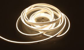
In recent years, a specific category of LED strip designed explicitly to eliminate any dotting effect has emerged: the so-called COB (Chip On Board) or "dot-free" strips. In these strips, instead of mounting separate individual SMD LEDs, LED chips are deposited directly onto the PCB in a continuous row, with such a high chip density (often 480–960 "emission points" per meter) that the visual result is that of a completely uniform luminous strip, similar to a linear fluorescent source.
COB strips have specific characteristics that distinguish them from high-density SMD strips:
| Characteristic | SMD 240 LED/m | COB dot-free |
|---|---|---|
| Luminous uniformity | Very high | Absolute |
| Typical luminous flux (lm/m) | 1800 – 2500 | 400 – 1200 |
| Efficiency (lm/W) | 100 – 150 | 60 – 100 |
| Minimum cutting length | 50 – 100 mm | 10 – 25 mm (or custom) |
| Dimmer compatibility | Standard PWM and CCT | Only specific dimmers |
| Typical CRI | 80 – 98 | 80 – 95 |
| Thermal management | Like high-density SMD | Critical: heat concentration |
| Relative cost | Medium-high | High |
| Minimum bend radius | 50 – 100 mm | 150 – 300 mm (rigid) |
| Diffuser required | Satin/opal | Not necessary |
The choice between SMD 240 LED/m strips and COB strips depends mainly on the required flux and application: COB strips are excellent for decorative or accent applications where absolute uniformity is more important than luminous power (up to 1200 lm/m), while SMD 240 LED/m strips are superior in applications where high flux is needed (>1500 lm/m) with high uniformity but not necessarily perfect. For medium-power architectural light cuts, SMD 240 LED/m strips remain the most versatile and high-performing choice.
How much does a 240 LED/meter strip heat up?
Heat management is the most critical and most frequently underestimated technical topic in installations with high-density LED strips. While for 60 LED/m strips with powers of 4.8–9.6 W/m the thermal issue is often manageable even without formal heat sinks, in 240 LED/m strips with powers of 20–24 W/m the thermodynamics of the installation must be considered a primary design element, not a secondary one. Ignoring thermal management in a 240 LED/m strip is the most common and most costly mistake that can be made, leading to premature failures, drastic drops in luminous flux, and, in extreme cases, fire risks in non-compliant installations.
Principles of thermodynamics applied to LED strips
An LED is a semiconductor device that converts electrical energy into light with an efficiency that, in the most modern versions, reaches 50–60%. This means that 40–50% of the absorbed electrical energy is dissipated as heat. In a 240 LED/m strip with a power of 24 W/m, the thermal power to be dissipated is about 10–12 W/m, a non-negligible figure that must be dissipated through thermal conduction to the substrate (PCB), then to the aluminum profile, and finally to the surrounding environment by convection and radiation.
The critical parameter for LED longevity is the junction temperature (Tj), i.e., the temperature at the interface between the semiconductor chip and the LED package. For the SMD chips used in 240 LED/m strips, the maximum absolute junction temperature (Tjmax) is typically 105–125°C. Above this value, degradation of the chip materials becomes rapid and irreversible. The relationship between junction temperature and LED operational life follows the Arrhenius law:
For every 10°C increase in junction temperature above the nominal design value, the average LED life is approximately halved. Starting from a theoretical life of 50,000 hours at Tj = 65°C, we obtain:
| Junction temperature Tj | Expected life (hours) | Reduction compared to nominal | Typical condition |
|---|---|---|---|
| 55°C | >70,000 | +40% | Strip with optimal heat sink |
| 65°C | 50,000 | Nominal | Reference condition |
| 75°C | 25,000 | -50% | Undersized aluminum profile |
| 85°C | 12,500 | -75% | Strip in channel without heat sink |
| 95°C | 6,000 | -88% | Strip embedded in insulating material |
| 105°C | 3,000 | -94% | Strip on closed plastic substrate |
| >115°C | <1,000 | -98% | Dangerous/failure situation |
Experimental temperature measurements: 240 LED/m strip in different configurations
To provide real and not just theoretical data, we report below the results of thermal measurements conducted on 240 LED/m, 24V, 20 W/m LED strips in different installation configurations. The measurements were carried out with an IR thermal camera at steady-state thermal conditions (after 30 minutes of operation) in a 25°C environment.
| Configuration | PCB temp. (°C) | External aluminum temp. (°C) | Estimated Tj (°C) | Expected life (hours) | Judgment |
|---|---|---|---|---|---|
| Strip on paper (only adhesive) | 84 | – | ~97 | ~6,500 | Critical |
| Strip on flat 1 mm aluminum | 71 | 64 | ~82 | ~15,000 | Insufficient |
| 16mm aluminum profile, without thermal paste | 58 | 51 | ~68 | ~45,000 | Good |
| 16mm aluminum profile, with thermal paste | 52 | 46 | ~62 | >50,000 | Excellent |
| 20mm aluminum profile, with thermal paste | 48 | 41 | ~57 | >60,000 | Excellent |
| 30mm aluminum profile (wide flange), with paste | 43 | 36 | ~51 | >70,000 | Excellent+ |
| Profile in drywall (insulating drywall) | 91 | – | ~106 | ~2,800 | Dangerous |
The data in this table clearly highlight three fundamental conclusions, let's see which ones.
- First: installing a 240 LED/m strip directly in drywall or on an insulating substrate is a technically incorrect and potentially dangerous choice, with junction temperatures exceeding the absolute limit of the chips.
- Second: a 16 mm wide aluminum profile already significantly reduces the temperature, bringing the expected life to acceptable values.
- Third: the use of conductive thermal paste between strip and profile further improves thermal performance by 10–15%, an increase that translates directly into a significantly longer operational life without any significant additional cost.
The concept of total thermal resistance and how to calculate it
For professionals who need a quantitative approach to thermal design, the concept of thermal resistance (Rth, expressed in °C/W) is the fundamental tool. The total thermal resistance of a strip-profile-environment system is calculated as the sum of the partial resistances in series:
Total Rth = Rth(LED-PCB) + Rth(PCB-profile) + Rth(profile-air)
Where:
- Rth(LED-PCB): internal thermal resistance of the LED towards the PCB, depends on the chip and its encapsulation. Typically 2–5°C/W for SMD 2835 chips.
- Rth(PCB-profile): depends on the quality of thermal contact. With standard adhesive: 8–15°C/W per cm². With thermal paste: 1–3°C/W per cm².
- Rth(profile-air): depends on profile geometry, aluminum conductivity (160–200 W/(m·K)), and heat exchange area. For typical profiles: 0.5–2°C/W per meter of profile.
A quality aluminum profile with 20 mm width and diffusion flange has an Rth to air of about 0.8°C/W per meter of profile. With a 20 W/m strip dissipating 10 W/m of heat, the temperature increase relative to the environment is: ΔT = 10 W/m × 0.8°C/W = 8°C per meter, which in a 25°C environment brings the profile to ~33°C — a perfectly acceptable value that guarantees junction temperatures well below the nominal 65°C.
Do high-density LED strips need an aluminum profile?
The question of whether high-density LED strips need an aluminum profile is one of those seemingly simple questions that hide an articulated technical answer. Strictly speaking, an LED strip works even without an aluminum profile: it turns on, emits light, responds to controller commands.
But the correct question is not whether it works, but whether it works over time with the expected performance. And the answer to this more rigorous formulation is unequivocal: for 240 LED/m high-density LED strips, the aluminum profile is not an optional accessory but an essential technical component of the system, on par with the power supply or the controller.
Analysis of consequences of installation without profile
To understand why the aluminum profile is necessary, it is useful to concretely analyze what happens to a 240 LED/m strip installed without a heat sink under real construction site conditions. The most common scenario in economical installations is applying the strip directly in the drywall seat with only adhesive, or in a plastic channel. In these cases, the following phenomena occur, with their respective timings:
| Phenomenon | Typical timing | Cause | Reversibility |
|---|---|---|---|
| 10–15% luminous flux drop | 1–3 months | Phosphor degradation due to heat | No |
| Chromatic shift (CCT shift) | 2–6 months | Differential phosphor degradation | No |
| Adhesive detachment | 1–4 months | Heat >80°C deteriorates acrylic | No (must be repositioned) |
| 30%+ flux drop | 6–12 months | Advanced LED chip degradation | No |
| Individual LED failure (dark dots) | 8–18 months | Burn-out due to overheating | No (replacement of entire section) |
| Diffuser/sheath yellowing | 3–9 months | Heat >70°C alters polymers | No |
| Total strip failure | 12–30 months | Short circuit due to heat | No (complete replacement) |
The data presented correspond to real construction site observations, verified on installations of 240 LED/m strips in drywall suspended ceilings without aluminum profile. The degradation pattern always follows the same sequence, with variations in timing depending on ambient temperature, daily hours of operation, and the specific quality of the strip.
The aluminum profile as a system component: fundamental functions
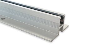
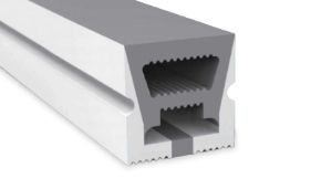
The aluminum profile for LED strips performs not one but four fundamental functions that all contribute to the quality of the installation: thermal dissipation, optical guidance, mechanical protection, and aesthetic integration. Analyzing each of these functions separately helps to understand why the profile is indispensable in professional installations.
Function 1 – Passive thermal dissipation: this is the primary function that we have already analyzed in detail in the previous chapter. Aluminum, with a thermal conductivity of 160–200 W/(m·K), is the most efficient material for passive dissipation available at accessible costs. A 16 mm wide aluminum profile reduces the PCB temperature by 15–30°C compared to the strip without heat sink, with a direct impact on operational life that can exceed 30,000 hours.
Function 2 – Optical guidance and luminous uniformity: LED strip profiles are designed with internal geometries that guide the light emitted by the strip, optimizing the angular distribution of emission. The internal chamber of the profile, combined with the diffuser, increases the effective distance between strip and observation surface, reducing P/D and improving uniformity. Some specialized profiles integrate polished aluminum reflective surfaces that increase luminous flux by 8–15%.
Function 3 – Mechanical protection: the LED strip, built on flexible PCB, is intrinsically fragile and subject to mechanical damage from pressure, excessive bending, impacts, and vibrations. The aluminum profile physically protects it during and after installation, preventing damage that could compromise the electrical circuit or create discontinuities in light emission.
Function 4 – Aesthetic integration: aluminum profiles for LED strips are available in dozens of different geometries — recessed, surface-mounted, angular, for stairs, for glass — and in different finishes (natural anodized, black anodized, white painted, gray painted). This variety allows the LED strip to be integrated into the architecture invisibly or as an explicit design element, depending on design intentions.
The aluminum profile as an element of regulatory compliance
An aspect that cannot be ignored in professional installations is that of compliance with electrical safety regulations.
The CEI EN 60598 standard (lighting equipment), applicable in Italy for all equipment incorporating LED sources, provides that the system as a whole must respect specific limits for accessible surface temperature and internal component temperature. For LED equipment installed in suspended ceilings or in construction elements, the EN 60598-2-24 standard specifies additional requirements for recessed equipment.
An installation of 240 LED/m strips without an appropriate aluminum profile in a drywall suspended ceiling may not comply with the requirements of this standard, with implications for insurance coverage in case of damage and for installer liability.
Types of aluminum profiles for LED strips: professional selection guide
The market for aluminum profiles for LED strips today offers such variety as to allow optimized solutions for virtually every architectural and installation application. The choice of the correct profile is not just a matter of aesthetics: dimensions, internal geometry, cover type, and installation method all have a direct impact on the thermal performance, optical properties, and durability of the LED system. This section offers a systematic guide to the main profile types, with specific selection criteria for each application category.
Classification by installation method
The first useful classification of aluminum profiles for LED strips concerns the installation method, which determines the final appearance and structural implications for the construction site:
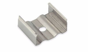
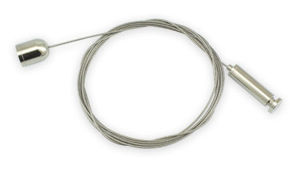
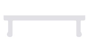
| Profile type | Fixing method | Installation thickness | Main application | Typical diffuser |
|---|---|---|---|---|
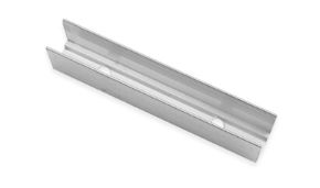
| Recessed (flush) | Embedded in drywall/wall | 12–20 mm | Light cuts, suspended ceilings | Opal/satin/micro-prismatic |
| Surface-mounted | Screwed to ceiling/wall | 8–15 mm | Exposed general lighting | Opal/satin/clear |
| Angular (corner) | Applied to 90° corners | 14–20 mm per side | Edge lighting, furniture | Satin/clear |
| Suspended (pendant) | Suspension cables | 30–60 mm | Direct/indirect lighting | Opal/micro-prismatic |
| For glass (glazing) | Clamped on glass | 6–12 mm | Glass shelves, illuminated mirrors | Clear/satin |
| For stairs (stair) | Recessed in step | 10–15 mm | Stair tread lighting | Satin/opal |
| Flag type (wing) | Wall-mounted with side flange | 20–40 mm | Washwall, indirect lighting | Opal/satin |
| For handrails | Integrated in handrail | Variable | Stair safety lighting | Satin/clear |
Technical selection criteria for profiles
Regardless of the chosen type, the selection of an aluminum profile for high-density LED strips must satisfy at least the following minimum technical requirements:
1. Minimum seat width: the internal seat of the profile must be at least 2 mm wider than the PCB of the strip to be installed. For 240 LED/m strips with 10 mm PCB, the seat must be at least 12 mm. Profiles with more generous seats (14–16 mm) allow greater positioning freedom and better dissipation.
2. Aluminum wall thickness: the thermal conductivity of the profile depends directly on the aluminum cross-sectional area available for heat conduction. Recommended minimum thicknesses: 1.5 mm for strips up to 15 W/m; 2.0 mm for 15–24 W/m strips; 2.5 mm or higher for 24+ W/m strips. Lower quality profiles with 0.8–1.0 mm walls do not guarantee adequate dissipation for high-density strips.
3. Aluminum alloy: most professional quality profiles are made of 6063-T5 aluminum alloy, which guarantees a thermal conductivity of about 200 W/(m·K) and excellent workability. Profiles made of inferior aluminum alloys or unclassified recycled aluminum can have significantly lower conductivity (down to 140 W/(m·K)), reducing dissipation effectiveness.
4. Internal seat finish: the internal finish of the profile chamber influences optical properties. A specular finish (polished or bright anodized aluminum) reflects light towards the diffuser, increasing extracted luminous flux by 5–15%. A matte or rough finish reduces this optical efficiency but may be preferable in some applications where unwanted reflections are to be avoided.
5. Diffuser fixing system: quality profiles use clip or snap systems for diffuser fixing that allow easy replacement during maintenance. Profiles with glued or permanently assembled diffusers should be avoided, as they do not allow diffuser replacement in case of damage or need to modify the diffusion type.
Specific profiles for drywall light cuts: essential characteristics
Recessed profiles for drywall light cuts deserve specific analysis as they represent the most used category in modern architectural applications. Their correct selection and installation is fundamental to achieve the desired aesthetic effect and to guarantee the necessary thermal performance.
A recessed profile for drywall light cuts must have: an upper flange of at least 3 mm that rests on the surrounding drywall; an internal chamber with a minimum depth of 15 mm for 240 LED/m strips; side fins for connection to drywall that do not interfere with cable routing; and a connection system to support brackets compatible with standard partition guides (CD 60/27 or similar).
High-quality profiles for drywall also include a putty masking system that facilitates cut finishing during drywall work, guaranteeing sharp edges and perfectly straight lines — a seemingly minor detail but fundamental for the final aesthetics of the work.
How to prevent LED strips from burning out after a few months: causes and remedies
Premature failure of LED strips is the most widespread problem in LED strip installations, and is almost always the result of avoidable errors that occur during design or installation. Understanding the root causes of premature failures is the indispensable prerequisite for systematically eliminating them, let's see what they are.
Cause 1: Overheating due to absence of heat sink
This is the most frequent cause of failure, responsible for over 60% of premature failures in 240 LED/m strips according to warranty statistics from major European manufacturers. The symptoms are progressive: gradual decrease in luminous flux in the first months, diffuser yellowing, appearance of localized dark areas (where LEDs have burned out), up to total failure. The remedy is exclusively preventive: always install the strip in an adequate aluminum profile, as detailed in the previous sections. There are no effective corrective remedies once thermal degradation has compromised the LED chips.
Cause 2: Undersized or uncertified power supply
The power supply is the second critical component for LED system longevity. An undersized power supply operates constantly at the limit of its nominal power, with high internal temperature that accelerates its degradation and produces voltage oscillations that stress the LEDs. The professional rule is to use a power supply with nominal power 20–30% higher than the total strip power. For a 240 LED/m strip, 20 W/m, 5 m length (total 100 W), the correct power supply is 120–130 W nominal, not 100 W.
Equally important is that the power supply be of certified quality: CE marking alone does not guarantee quality, as it is susceptible to counterfeiting. The parameters to verify are: efficiency > 85% (preferably > 90%), power factor > 0.90, output ripple <50 mV, integrated OVP (overvoltage) and OCP (overcurrent) protections, certified operating temperature (-20/+50°C minimum), and UL, TÜV or equivalent certifications for the target market.
| Strip length (m) | Strip power (W/m) | Total power (W) | Minimum power supply (W) | Recommended power supply (W) |
|---|---|---|---|---|
| 1 | 20 | 20 | 24 | 30 |
| 2 | 20 | 40 | 48 | 60 |
| 3 | 20 | 60 | 72 | 75–100 |
| 5 | 20 | 100 | 120 | 150 |
| 8 | 20 | 160 | 192 | 200–250 |
| 10 | 20 | 200 | 240 | 250–300 |
Cause 3: Excessive voltage drop in long runs
Voltage drop along the LED strip is an inevitable physical phenomenon that increases with conductor resistance (dependent on PCB cross-section), the current flowing, and the run length. For 12V strips, already at 5 meters distance from the power supply the voltage drop can reach 10–15%, producing a visible brightness drop in the final part of the strip. In 240 LED/m strips, particularly sensitive due to the high absorbed current, this phenomenon is amplified.
Practical remedies for managing voltage drop in long runs are: use 24V strips instead of 12V (drop halved under all other equal conditions), power the strip from both ends for lengths over 5 m, use connection cables between power supply and strip with minimum cross-section of 1.5 mm² and preferably 2.5 mm² for power supply-strip distances over 3 m, never connect strips in series but always in parallel to the power supply.
Cause 4: Humidity and condensation
Humidity is the nemesis of LED strips in all applications where the strip is not adequately protected. IP20 classified strips have no protection against moisture ingress and must not be used in environments with relative humidity above 70% under static conditions, or in any environment where condensation may occur. Moisture damage is typically irreversible and manifests as connector oxidation, PCB corrosion, LED failure due to phosphor contamination, and short circuits.
Selection of the correct IP rating is fundamental: IP44 for generic humid environments (bathrooms, kitchens), IP65 for exposure to occasional water jets, IP67 for temporary immersion, IP68 for permanent immersion. In installations in contact with drywall structures on external walls, even when the strip is inside, it is good practice to use at least IP44 or IP65 to protect against seasonal condensation humidity.
Cause 5: Incompatible dimming
Dimming LED strips with incompatible dimmers is an underestimated but frequent cause of failure, especially in residential contexts where an attempt is made to recycle existing dimmers designed for incandescent or halogen lamps. Traditional phase-cut dimmers (TRIAC) are completely incompatible with most LED strip power supplies and can cause: brightness oscillations (flickering), electrical noise, abnormal heat in the power supply, and premature failure of both the dimmer and the power supply and strip.
For correct dimming of 240 LED/m strips, compatible solutions are: low-voltage PWM dimmers (between power supply and strip, DC voltage); 0–10V or DALI signal dimmable power supplies for professional installations; TRIAC-dimmable systems only with power supplies specifically certified as TRIAC-compatible. Verification of dimmer-power supply compatibility must always be carried out before installation, consulting the technical data sheets of both components.
Cause 6: Excessive length of single run
Connecting in series a length of strip greater than the maximum recommended by the manufacturer for a single run is an error that produces excessive voltage drop, non-uniform heating, and component stress. The maximum length for a single run varies depending on voltage, power per meter, and PCB cross-section:
| Voltage | Power (W/m) | PCB cross-section | Max run (m) | Voltage drop at max run |
|---|---|---|---|---|
| 12V | 20 | Standard (1oz Cu) | 3 | ~8% |
| 12V | 20 | Heavy (2oz Cu) | 5 | ~8% |
| 24V | 20 | Standard (1oz Cu) | 7 | ~6% |
| 24V | 20 | Heavy (2oz Cu) | 10 | ~5% |
| 24V | 24 | Heavy (2oz Cu) | 8 | ~6% |
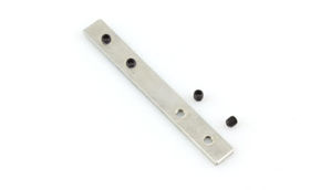
For installations requiring greater lengths, the correct solution is subdivision into separately powered segments, with each segment connected directly to the power supply via its own cables. The segments are then optically connected with junction connectors that do not carry current but maintain the visual continuity of the strip.
LED strip overheating: diagnosis, prevention, and intervention
Overheating of LED strips is a problem that can manifest acutely (strip suddenly stops working after a few minutes of operation) or chronically (strip progressively degrades over months). Both manifestations have identifiable causes and applicable remedies, but require different diagnostic approaches. This section provides a structured protocol for diagnosing, preventing, and remedying overheating in high-density LED strip installations, with particular attention to the needs of electricians and technicians operating on construction sites.
Overheating diagnosis: tools and methodology
Correct diagnosis of overheating in an LED strip requires measuring temperature at specific points in the system. The most useful tools for this diagnosis are: the IR thermal camera (significant investment but indispensable for accurate diagnosis), the IR pointer pyrometer (economical, accurate for point measurements), and the thermocouple probe to be applied directly to the PCB (requires physical access to the strip).
The diagnostic methodology involves measuring temperature at three critical points: on the PCB directly above a lit LED (hottest point), on the external surface of the aluminum profile (heat sink temperature), and on the surrounding environment (reference temperature). The difference between PCB temperature and ambient temperature gives the measure of total ΔT, to be compared with reference values from Table 11 to assess whether dissipation is adequate.
Overheating symptoms and their diagnostic interpretation
| Observed symptom | Possible cause | Diagnostic test | Intervention |
|---|---|---|---|
| Strip turns off after 10–30 min | Power supply thermal protection | Measure power supply temp. | Improve power supply ventilation |
| Strip turns off in specific area | Local strip overheating | Thermal camera on strip | Add local heat sink |
| Progressive brightness drop | Thermal LED degradation | Measure flux vs. nominal | Improve dissipation; replace strip |
| Color variation (warmer/cooler) | Chromatic shift from heat | Measure CCT with colorimeter | Replace strip; thermal intervention |
| Black LEDs (dark dots) | Local burn-out from overheating | Visual inspection + thermal camera | Replace section or entire strip |
| Burning smell | Severe component overheating | Immediate shutdown; inspection | Shut down system; electrical investigation |
| Yellowed diffuser | Excessive heat (>70°C) | Measure diffuser temperature | Increase strip-diffuser distance; heat sink |
Thermal improvement interventions on existing installations
When intervening on an existing installation that presents overheating problems, the available options depend on strip accessibility and the nature of the problem. In drywall installations, access to the strip is generally limited or requires masonry work, which makes correct thermal design even more important during initial installation.
When intervention is possible, practical options include: retroactive insertion of aluminum profiles (possible if the cut chamber allows it), application of thermal pastes between strip and existing substrate, permanent power reduction through dimming (20–30% power reduction significantly reduces temperature), and replacement with higher density but lower power strips that produce the same luminous flux with less heat.
High-density LED longevity: determining factors
The lifespan of a high-density LED strip is one of the topics on which there are the greatest discrepancies between manufacturers' commercial claims and actual performance in installations. Technical data sheets often report average lives of 50,000 hours (corresponding to over 17 years of use at 8 hours/day), but these figures refer to laboratory test conditions often very different from real construction site operating conditions. Understanding which factors determine the actual lifespan of an LED strip and how to intervene on them is fundamental to guarantee expected long-term performance.
The IES TM-21 standard and the L70B50 parameter
The industrial reference parameter for LED lifespan is defined by the IES TM-21 standard of the Illuminating Engineering Society. The L70B50 parameter indicates the time within which 50% of products in a batch reach a luminous flux equal to 70% of the initial value. This parameter is more significant than simple "average life" because it considers the statistical distribution of degradation across the entire product population.
For quality professional 240 LED/m strips, the L70B50 values declared by major manufacturers range from 30,000 to 75,000 hours. The huge difference between these values depends mainly on three factors: quality of LED chips used, quality of encapsulation process and, above all, operating thermal conditions. As already analyzed, every 10°C increase in junction temperature approximately halves operational life, making thermal management the dominant factor in determining actual lifespan.
The five factors determining actual lifespan
The five factors that determine the actual lifespan of a high-density LED strip, in order of importance, are: operating junction temperature (already analyzed in detail), the quality of phosphors used in encapsulation, the quality of the fixing substrate and assembly process, environmental conditions (humidity, UV, contaminants), and the dimming regime.
Phosphors are the luminescent materials that convert the blue light of the LED chip into white light. The quality of phosphors determines not only the initial conversion efficiency but also stability over time: lower quality phosphors degrade more rapidly, producing the typical chromatic shift towards colder or warmer tones observed in aged strips. Manufacturers that specify phosphors from qualified suppliers guarantee certified chromatic stability typically expressed as Δu'v' < 0.007 for 6,000 hours at accelerated temperature according to LM-80.
PWM dimming, when used at frequencies below 1 kHz, produces cyclic thermal stresses on LED chips that accelerate degradation of contacts between chip and substrate. For installations with intensive dimming (hotel environments, retail with variable lighting throughout the day), it is preferable to use high-frequency PWM dimmers (≥ 2 kHz) or, even better, constant current dimmers that completely eliminate cyclic thermal stress.
Practical strategies to maximize lifespan
Practical strategies to maximize the lifespan of high-density LED strips are articulated on two levels: design choices to be made before installation, and management practices to be adopted during the operational life of the system.
At the design level: choose strips with certification and documented life calculation, size the aluminum profile to achieve a PCB temperature < 55°C under normal operating conditions, use quality power supplies with integrated protections, specify strips with IP rating adequate to the environment, and pre-size the system to operate at 80% of maximum flux, leaving margin to compensate for degradation over time without early replacement interventions.
At the management level: avoid keeping strips on 24/7 when not necessary, since reducing operating hours proportionally extends life, implement control systems with presence sensors that turn off strips when rooms are empty, periodically verify (every 2–3 years) operating temperature with thermal camera, and keep aluminum profile surfaces clean to not reduce their dissipation efficiency with dust accumulation.
12V vs 24V high-density LED strips: which voltage to choose and why
The choice between 12V and 24V supply voltage for high-density LED strips is a technical decision with significant implications on multiple aspects of the system: from maximum run length, to quality of luminous uniformity, to required cable cross-section, up to system safety.
Although both voltages are widely available on the market and supported by the vast majority of 240 LED/m strips, technical analysis leads to a clear conclusion: for professional applications with high-density LED strips, the 24V system is almost always superior, and in many cases it is the technically correct choice in an unequivocal manner.
Comparative analysis 12V vs 24V
| Parameter | 12V System | 24V System | Advantage |
|---|---|---|---|
| Current at 1m of strip (A) | 1.67 A | 0.83 A | 24V: current halved |
| Voltage drop over 5m (with 1oz PCB) | ~1.2V (10%) | ~0.6V (2.5%) | 24V: 4x lower drop |
| Maximum single-feed run length | 3–5 m | 7–10 m | 24V: 2x longer runs |
| Recommended cable cross-section (5m strip) | 2.5 mm² | 1.5 mm² | 24V: thinner cables |
| Luminous uniformity over 5m | Visible difference at end of run | Uniform throughout length | 24V: superior uniformity |
| Safety (SELV regulation) | SELV (<30V AC/60V DC) | SELV (<30V AC/60V DC) | Equal: both SELV |
| Product availability | Very high | Very high | Equal |
| Power supply cost (same W) | Slightly lower | Slightly higher | 12V: slight cost advantage |
| Home automation controller compatibility | Excellent | Excellent | Equal |
| Resistive cable losses 5m (2.5mm²) | ~3 W | ~0.75 W | 24V: 4x less losses |
When is it acceptable to use 12V for 240 LED/m strips
There are specific situations where the 12V system may be acceptable even for 240 LED/m strips: installations with very short runs (less than 2 meters) where voltage drop is negligible, retrofitting in existing systems already wired at 12V where power supply modification is not economically justified, applications with moderate power strips (< 12 W/m) that limit absolute current, and mobile or temporary installations where 12V battery power is necessary for practical reasons. Outside these specific cases, the choice of 24V for 240 LED/m strips is technically mandatory to guarantee luminous uniformity and system durability.
Cable sizing for 24V systems with 240 LED/m strips
A common error even in 24V installations is the undersizing of connection cables between power supply and strip. The CEI 64-8 standard provides conductor capacity tables based on temperature and installation method, but for LED installations it is useful to have simplified practical rules based on typical lengths:
| Strip length (m) | Total current (A) | Cable length (m) | Minimum cross-section (mm²) | Recommended cross-section (mm²) |
|---|---|---|---|---|
| 2 | 1.67 | ≤2 | 0.75 | 1.0 |
| 5 | 4.17 | ≤3 | 1.5 | 1.5 |
| 10 | 8.33 | ≤5 | 2.5 | 2.5 |
| 15 | 12.5 | ≤5 | 4 | 4 |
| 20 | 16.7 | ≤5 | 6 | 6 |
Best LED strip for drywall light cuts: technical application guide
Light cuts in drywall represent the most emblematic and at the same time most technically demanding application of high-density LED strips in contemporary architecture. This technique, which consists of creating linear fissures in suspended ceilings or drywall walls through which light emitted by the strip illuminates the adjacent surface, creating grazing reflection effects and architectural light, has become the aesthetic trademark of medium-to-high level interior design projects.
However, the quality of the final result, in terms of luminous uniformity, absence of dots, color balance, and durability over time critically depends on the choice of LED strip, profile, and cut geometry.
Light cut geometry: critical parameters
The geometry of the light cut determines three fundamental parameters for the quality of the optical result: the strip-diffuser distance (P/D parameter), the angle of light emission towards the wall or ceiling, and the visibility of the strip itself through the cut opening. Optimal design of a light cut requires precisely defining these three parameters according to the desired effect.
The main types of light cuts in drywall are: the horizontal cut on lowered suspended ceiling with light toward wall (washwall effect) which requires a chamber of at least 50 mm between strip and cut edge to avoid direct glare, the perimeter cut on lowered suspended ceiling with light upward (moon/cove lighting effect) which requires a chamber of at least 100 mm between strip and main ceiling for uniform illumination, and the vertical cut on wall with light toward floor or ceiling, which requires specific profile geometry to correctly direct the light.
| Cut type | Recommended strip | Profile | Minimum chamber | Recommended flux (lm/m) | Diffuser |
|---|---|---|---|---|---|
| Horizontal washwall | 240 LED/m, 24V | Recessed with flange | 50 mm | 1500–2000 | Satin/micro-prismatic |
| Perimeter cove lighting | 120–240 LED/m, 24V | Flat recessed | 100 mm (toward ceiling) | 1000–1800 | Opal or none |
| Vertical wall cut | 240 LED/m, 24V | Directional recessed | 30 mm | 1800–2500 | Satin |
| Illuminated baseboard | 120–240 LED/m, IP44 | Recessed for floor | 15 mm | 500–1000 | Satin/opal |
| Double cut (up/down) | 240 LED/m, 24V | Double symmetric profile | 60 mm (per side) | 2000–2500 | Satin |
The glare issue: UGR and design solutions
A technical aspect often overlooked in light cuts is glare control, evaluated through the UGR (Unified Glare Rating) parameter of EN 12464-1 standard on workplace lighting. Although light cuts are predominantly decorative, in applications where the environment is also a workplace (open space offices, meeting rooms, showrooms) UGR control is mandatory by regulation.
LED strips exposed directly through the cut, even with diffuser, typically have high luminance that can contribute significantly to the environment's UGR. Solutions to control glare in light cuts are: widen the cut and recess the strip to reduce the direct viewing angle, use diffusers with reduced transmission (denser opals that reduce visible luminance), integrate masking fins that prevent direct viewing of the strip from above or sides; and orient the cut perpendicular to the primary sight lines of occupants.
Integration with drywall systems: construction details
The technical integration of LED strip profiles in drywall systems requires careful planning involving both the designer and the construction company. The main aspects to coordinate are: sizing the metal support structure of the suspended ceiling to support the additional weight of the aluminum profile and strip, routing electrical cables in the technical chamber of the suspended ceiling to the power point, with adequate sizing, the construction tolerance of the drywall cut (typically ±1 mm) to ensure the profile is perfectly flush with the drywall surface, and finishing the cut with putty or masking profiles that create sharp and visually continuous edges along the entire installation length.
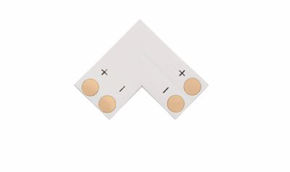
A fundamental construction detail is the management of corners in perimeter installations: 90° angles in cove installations require profiles with 45° cuts or specific angular connectors that maintain the optical continuity of the luminous strip. The quality of these angular details is often the point that differentiates a professional-level installation from an artisanal one.
Professional installation guide for high-density LED strips
Professional installation of high-density LED strips is a process that requires attention to detail at every stage, from material receipt on site to final testing. Even the best LED strip on the market produces unsatisfactory results if installed incorrectly: the most common error does not concern product choice but its installation, and installation errors are almost always irreversible without dismantling the installation. This section presents a structured operational guide by phase, designed to be used as a reference checklist on site.
Phase 1: material verification and preparation
Before starting any installation, it is essential to verify the correspondence between delivered material and project specification. The parameters to verify are: nominal voltage (12V or 24V, verify on roll label), power per meter (W/m, verify it matches specified), number of LEDs per meter (visually verify density), cutting length (verify where cutting points are on label or strip itself), color temperature (verify CCT code: 27K, 30K, 40K, 65K), IP rating (verify declared protection level). It is also fundamental to verify that strips from the same production batch (same chromatic binning) are used in the same installation, to avoid visible chromatic differences between adjacent segments.
Phase 2: surface and profile preparation
Preparation of the installation surface is fundamental for adhesion quality and thermal contact. The aluminum profile must be cleaned of grease, dust, and surface oxides with a clean cloth soaked in isopropanol (70% IPA): this operation, often skipped on site, significantly improves adhesive bonding and thermal contact with thermal paste. The cutting of the profile to exact length must be done with metal saw or cutter with aluminum blade, ensuring perpendicular cuts ±0.5° for correct joining of adjacent segments.
Phase 3: applying the strip in the profile
Applying the strip in the profile is the most delicate operation of the installation. The correct steps are:
- apply a thin continuous line of conductive thermal paste (type Arctic MX-4 or equivalent, conductivity ≥ 6 W/(m·K)) on the profile seat before applying the strip;
- remove the protective film from the adhesive on a 10–15 cm segment at a time and not over the entire length in a single operation;
- apply the strip in the seat with uniform pressure distributed over the entire PCB width avoiding point pressures that could create micro-cracks on the PCB;
- verify the absence of air bubbles between strip and profile;
- never cut the strip at points other than the indicated cutting marks.;
Phase 4: electrical connections
Electrical connections are the most critical point for safety and reliability of the installation. The fundamental rules are:
- never solder directly on the PCB pads of the strip with soldering iron over 30W or for more than 3 seconds;
- to avoid thermal damage to the LED chip closest to the pad;
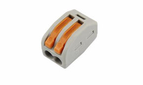
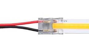
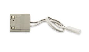
- use certified pressure connectors (snap-in) for the type of strip (verify that connector width matches strip width);
- for quality permanent connections;
- prefer soldering with low-melting-point tin (type SAC305) on well-prepared pad surfaces;
- protect connections with heat-shrink sleeves or IP-rated sealed terminals if installed in humid environments;
- verify polarity before applying voltage (positive pole is almost always indicated on PCB with "+" symbol or with a wider dash).
Phase 5: testing and performance verification
Pre-closure testing of the installation must be carried out before closing the suspended ceiling or covering the profile with the final diffuser.
The tests to carry out are:
- visual verification of luminous uniformity along the entire length (verify absence of darker or lighter areas);
- voltage measurement at strip ends with multimeter to verify voltage drop (must be < 5% of nominal voltage);
- profile temperature measurement with IR pyrometer after 30 minutes of full-power operation (must be < 55°C in 25°C environment);
- verification of dimmer operation over the entire 0–100% range (verify absence of flickering with smartphone slow-motion camera);
- and check of chromatic uniformity along the strip (verify absence of areas with different color temperature).
High-density LED strips in architectural light design
High-density LED strips have transformed the practice of architectural light design, opening compositional possibilities that were technically unachievable with traditional light sources. The ability to distribute continuous and uniform light along architectural lines of any length, with high chromatic quality and contained thickness, has made 240 LED/m strips the preferred tool of light designers for creating impactful architectural effects, from grazing light that enhances surface textures to indirect light that shapes the volumetric perception of spaces.
Calculating required luminous flux for cove lighting
Cove lighting, indirect lighting via perimeter niche LED strips that illuminate upward toward the ceiling, requires calculation of the necessary luminous flux to achieve the desired illuminance on the ceiling. The basic calculation is performed with the utilization factor (UF) method, simplified for typical residential and commercial installations.
For a cove lighting installation in a 6×8 m room with 2.8 m ceiling height, white ceiling (ρ = 0.85) and light wall (ρ = 0.50), desiring to illuminate to 150 lux average on the ceiling, the calculation proceeds as follows:
ceiling area = 48 m²
total required flux (considering UF = 0.35 for indirect cove lighting) = 150 lux × 48 m² / 0.35 = 20,571 lm
room perimeter ≈ 28 linear m; required flux per linear meter = 20,571 / 28 ≈ 735 lm/m.
A 240 LED/m strip with 1800 lm/m flux installed with dimmer at 40% would therefore be sufficient, with the advantage of a wide adjustment margin upward for brighter scenes.
The washwall effect
The washwall effect, grazing illumination of a vertical wall with horizontal LED strip that creates uniform luminous distribution from top to bottom, requires precise positioning of the strip in relation to the wall. The optimal distance of the strip from the wall to achieve maximum luminous uniformity depends on the strip emission angle (120° typical) and the desired photometric distribution.
For a strip with 120° emission angle, positioned in a profile with asymmetric flange at 45° to vertical, at 30 cm from the wall, maximum illuminance occurs at about 15–20 cm below the profile, with a distribution that extends uniformly for about 1.8–2.0 m downward. This calculation demonstrates that for effective washwall on walls of 2.7–3.0 m height, the strip must be positioned no more than 30–40 cm from the wall, a distance that imposes precise geometric constraints on the designer.
Applications in retail and museums
In retail and museum applications, high-density LED strips must satisfy specific photometric requirements that go beyond simple uniformity: color rendering (CRI) must be ≥ 90 for quality retail and ≥ 95 for art galleries, according to recommendations of the Commission Internationale de l'Éclairage (CIE). Color temperature must match the chromatic palettes of the installations: 2700–3000K for warm and intimate environments (jewelry, premium clothing), 3500–4000K for neutral environments (general retail, cosmetics), 4000–5000K for technical environments (electronics, sportswear).
An additional parameter of great importance in museum applications is the UV content in emitted light: modern LED strips have negligible UV content compared to fluorescent or halogen sources, but strips with CRI > 95 based on broadband phosphors may have higher residual UV. For applications with artworks or light-sensitive materials, it is advisable to verify that specified strips have certified UV content < 75 μW/lm, according to recommendations of UNI EN 16141 standard for preventive conservation.
Regulations and safety
Professional installation of high-density LED strips in Italy is governed by an articulated regulatory framework comprising European directives, CEI technical standards, and national provisions on electrical safety and energy efficiency. Knowledge of this regulatory framework is not only a formal duty of the installer but has direct implications on civil and criminal liability in case of accidents, on work insurance coverage, and on installation compliance with control authority verifications.
Reference regulatory framework
The main technical standards and directives applicable to high-density LED strip installations are as follows. The Low Voltage Directive 2014/35/EU (implemented in Italy with Legislative Decree 86/2016) establishes essential safety requirements for electrical products, including LED strip power supplies, which must be CE marked in compliance with this directive. The EMC Directive 2014/30/EU concerns electromagnetic compatibility of products, applicable to switching power supplies (SMPS) used for LED strips, which must respect conducted and radiated emission limits defined by EN 55032 standard.
The CEI 64-8 standard (Electrical user installations) defines requirements for design and realization of low-voltage electrical installations, including LED installations in civil buildings. The CEI EN 60598 standard defines requirements for lighting equipment, including LED systems. For LED strips in drywall systems, the EN 13501-1 and EN 13501-2 standards on fire reaction of construction materials also apply: aluminum profiles have A1 classification (non-combustible) while PVC or silicone sheaths of IP strips have variable classifications that must be verified according to the fire resistance class required by the building.
SELV classification and extra-low voltage safety
A relevant regulatory advantage of 12V and 24V LED strips is that these voltages fall within the SELV (Safety Extra-Low Voltage) classification defined by the EN 61140 standard, which provides simplified installation requirements compared to mains voltage circuits (230V AC). In a SELV circuit: grounding of the circuit is not required, protection against indirect contact (differential) is not required, and protection against direct contact is sufficient with only prevention of access to bare conductors. This significantly simplifies the design and installation of the secondary circuit (power supply-strip), while requiring that the primary circuit (230V AC to power supply) respects all normal prescriptions of CEI 64-8.
Declaration of conformity and installation documentation
For installations in buildings subject to declaration of conformity obligation (Ministerial Decree 37/2008), the installer must produce the Declaration of Conformity (DdC) of the installation, attaching the project or electrical diagram, technical report, and list of materials with their respective certifications. For high-density LED strips, the documents to acquire from suppliers and attach to the DdC include: product technical data sheets with relevant certifications (CE, ENEC, TÜV as applicable); manufacturer installation manual; and LM-80 certification for LED lifespan, if available. Retention of this documentation is important not only for the DdC but also for future management of warranties on installed products.
Market data and trends in the high-density LED strip sector
The high-density LED strip market is a rapidly growing segment within the broader LED lighting market, driven by both technological factors (continuous reduction in production costs of high-quality LED chips) and design factors (growing sophistication of aesthetic demands in contemporary architecture). An analysis of market trends provides professionals with useful context for specification decisions and for anticipating technological developments that will influence installations in coming years.
Size and growth of Italian and European market
The European LED strip market reached an estimated value of 2.8 billion euros in 2024, with high-density strips (≥120 LED/m) representing about 42% of total volume in value (compared to 28% in 2020). Growth of the high-density segment was 18% annually in the 2021–2024 triennium, significantly higher than the average growth of the overall LED market (+9% in the same period). In the Italian market, 240 LED/m LED strips recorded 23% growth in 2023, with the professional channel (installers, construction companies, technical distributors) representing 68% of volumes.
| Category | LED/m | Volume share (%) | Value share (%) | 2024 vs 2023 trend |
|---|---|---|---|---|
| Low density | 30–60 | 38% | 22% | -5% |
| Medium density | 120 | 28% | 25% | +8% |
| High density | 180–240 | 27% | 38% | +23% |
| Ultra density / COB | ≥480 | 7% | 15% | +41% |
Emerging technological trends
The technological trends shaping the future of high-density LED strips include several innovations that will become market standards in the next 3–5 years. The most significant is the advancement of SMD 2110 and 1808 chips as the dominant standard in 240+ LED/m strips, with luminous efficiencies already exceeding 180 lm/W in top versions and tending toward 200 lm/W by 2027. This evolution allows obtaining increasingly higher luminous fluxes without increasing power (and therefore heat) per meter.
The second relevant trend is the diffusion of Tunable White LED strips (adjustable white) at high density, which integrate chips of two or more color temperatures in the same PCB (typically 2700K + 6500K, or 2700K + 4000K + 6500K) controllable separately to dynamically vary the emission color temperature from 2700K to 6500K while maintaining constant flux. These strips, once available only in low-density versions, are now available at 240 LED/m with optical quality equivalent to monochromatic strips of equal density.
The third trend is the integration of high-density LED strips into Human Centric Lighting (HCL) systems, which provide automatic adjustment of color temperature and intensity according to time of day, season, and physiological needs of occupants. The availability of 240 LED/m Tunable White strips with CRI ≥ 90 and DALI-2 or Bluetooth mesh drivers is the technical prerequisite for implementing HCL with the aesthetic quality required by contemporary architectures.
Price evolution and market accessibility
The cost of high-density LED strips has decreased significantly in recent years, making these solutions increasingly competitive even in the mid-price range. A 240 LED/m LED strip with CRI ≥ 90 and 24V had a cost of about 35–45 euros/meter in 2019; in 2024 the same performance level is available at 18–28 euros/meter in the professional channel. This reduction of about 40% in five years has shifted the economic balance point between standard and high-density strips, making the choice of superior quality economically accessible even for mid-range projects.
FAQ
We collect in this section the most frequent questions that architects, professional electricians, and light designers ask Ledpoint.it technicians regarding high-density LED strips, with the aim of offering a quick practical reference for situations that arise daily on construction sites and in studios.
Questions on product selection
Q: Can I use a 240 LED/m strip to replace 1800 mm linear neon tubes without modifying the existing profile?
A: It depends on the dimensions of the existing profile. If the profile is aluminum with seat ≥ 10 mm wide and depth ≥ 12 mm, the 240 LED/m strip can be installed in the existing seat verifying that the power supply is adequate for the new power. If the profile is plastic, it must be replaced: the power of a 240 LED/m strip (20 W/m) would cause overheating in any plastic profile. The cutting length of the strip must be compatible with the neon length (1800 mm): verify that 1800 mm is a multiple of the specific strip cutting length.
Q: Is there a difference between a 240 LED/m strip at 12 euros/m and one at 28 euros/m? Is it worth spending more?
A: Yes, the difference is substantial and manifests on multiple parameters. Lower-end strips use lower quality LED chips with actual luminous efficiency often 20–30% lower than declared, actual CRI of 75–80 (declared 80+), MacAdam Step ≥ 5, and higher thermal resistance leading to higher junction temperatures at equal power. Premium quality strips offer verified efficiency, actual CRI ≥ 90, MacAdam Step ≤ 3, and certified L70B50 lifespan >50,000 hours. In a construction site installation, the cost difference between the two categories is generally less than 5% of the total intervention cost (including labor, profiles, power supplies, drywall), while the difference in final result quality is clearly perceptible to the client.
Q: Can a 240 LED/m IP65 strip be installed outdoors?
A: IP65 guarantees protection against water jets but not against immersion, UV rays, and prolonged low temperatures. For outdoor installations exposed to direct precipitation, IP65 classification is the minimum, preferring IP67 or IP68. But UV resistance of the sheath is an additional parameter not included in the IP rating: always verify that the sheath is classified UV-resistant according to EN 50289 standard or equivalent. For coastal areas with high salinity, choose strips with silicone sheath (more corrosion-resistant) instead of PVC. The minimum operating temperature of the strip must be verified for alpine or Po Valley climates with frequent frosts.
Questions on installation
Q: Can I connect different LED strips in the same DALI control system?
A: Yes, provided the power supplies are DALI-compatible and correctly addressed. The DALI system (Digital Addressable Lighting Interface) supports up to 64 devices (power supplies) on a single loop, with each device individually or group addressable. It is possible to mix strips of different densities (60 and 240 LED/m) in the same DALI system provided both power supplies are DALI-certified and programmed with different addresses. For systems with more than 64 power supplies, it is necessary to subdivide into multiple DALI loops or use DALI-2 systems with network gateways.
Q: Can Wago terminal blocks be used to connect 24V LED strips?
A: Yes, WAGO 221 or 222 series terminal blocks are suitable for 24V DC connections up to 32A (for the 2.5 mm² version), well above the typical currents of LED strips. They are particularly useful for intermediate power connections in long-run installations and for branching from a main cable to multiple strip segments. The only precaution is to verify that the terminal block used is certified for DC use: some versions are certified only for AC, although in practice they also work in DC at the typical SELV voltages of LED strips.
Q: Is it necessary to seal the ends of IP65 strips after cutting?
A: Yes, absolutely. Cutting the IP65 strip exposes the PCB and solder pads to the environment: in the absence of sealing, moisture enters the cut end and can cause PCB corrosion and pad short circuits. Correct sealing is performed with: specific end caps for IP65 LED strips (available from LED material suppliers); two-component epoxy resin applied with syringe in open ends; or moisture-resistant self-amalgamating tape tightly wrapped around the end for at least 30 mm. Construction silicone is not suitable: it does not adhere well to PCB and strip coating long-term.
Questions on design
Q: How do you calculate the number of power supplies needed for a system with 45 m of 240 LED/m strips at 24V?
A: For 45 m of 20 W/m strip: total power = 45 × 20 = 900 W. With 25% safety factor: total power supply power = 900 × 1.25 = 1125 W. Considering maximum runs of 8 m for heavy duty 24V strips: number of segments = ⌈45/8⌉ = 6 segments. With 6 segments, each segment absorbs about 150 W, so you can use one 200W power supply per segment (6 total power supplies), or aggregate segments with 400W power supplies (3 power supplies) if distribution cables have adequate cross-section. The second option is more economical but requires careful cabling design.
Q: How do you avoid flicker in dimmed LED strips: at what frequency must the dimmer work?
A: Flicker in dimmed LED strips is caused by PWM (Pulse Width Modulation) used by dimmers to vary power. The human eye perceives flicker up to about 80–100 Hz; cerebral photosensitivity extends up to 200–400 Hz. To eliminate any risk of visual disturbance, professional LED strip dimmers must operate at a PWM frequency ≥ 1000 Hz (1 kHz), with premium versions operating at 2000–20,000 Hz. Frequencies below 400 Hz are unacceptable in any professional application due to the combination of health risk and potential interference with video recording systems. Flicker index (FI) and percent flicker (PF) are the parameters standardized by IEEE 1789-2015 to objectively evaluate the biological risk of flicker in lighting systems.
High-density LED strips? Yes, but after careful analysis.
240 LED/m strips are not simply better strips than standard strips: they are components of a more complex integrated system that requires a systemic approach to design, where every choice influences the others and where optimization of the final result is achieved only through technical coherence among all components. This approach is based on five fundamental principles that we summarize.
First principle — Correct density for every application: not every application requires 240 LED/m. The practical rule is: if the strip is visible to the observer at less than 2 meters, or if it is installed in a profile with chamber < 30 mm, choose 240 LED/m. For indirect light applications with large strip-surface distance, 120 LED/m may be sufficient. For purely functional non-visible applications, 60 LED/m is often appropriate and economically correct.
Second principle — Aluminum profile is mandatory: for any 240 LED/m strip with power ≥ 15 W/m, the aluminum profile is not an optional accessory but an essential technical component of the system. Correctly sizing the profile (width ≥ 16 mm, wall thickness ≥ 1.5 mm, 6063-T5 alloy) and applying thermal paste between strip and profile are non-negotiable operations to guarantee expected operational life.
Third principle — 24V for runs over 3 meters: the choice of 24V voltage instead of 12V for 240 LED/m strips with runs over 3 meters is not preference but technical necessity to guarantee luminous uniformity along the entire length. The small cost difference of 24V power supplies compared to 12V is amply justified by the superior quality of the result.
Fourth principle — Correct power supply with 25% margin: a power supply sized exactly to the strip power operates under continuous thermal stress conditions that reduce its life and can cause unwanted voltage variations. The 25% margin is not waste but investment in system reliability and longevity.
Fifth principle — Product quality is worth the additional cost: in a professional installation, the cost difference between medium-quality and premium-quality LED strips is typically less than 5% of the total intervention cost. The difference in result quality, installation durability, and client satisfaction is incomparably greater. Specifying products with CRI ≥ 90, MacAdam Step ≤ 3, and certified L70B50 lifespan > 50,000 hours is the correct way to protect the professional reputation of the installer and designer.
The continuous growth of the high-density LED strip segment reflects a market maturation and an increasingly widespread technical awareness among professionals. Those who have invested in thorough understanding of these products are able to respond to the increasingly sophisticated demands of consumers and to differentiate themselves in a competitive market through the certifiable quality of their work.
And if there is any doubt about the product, it is always possible to contact Ledpoint support!